background image

129

Setup Menu Tab

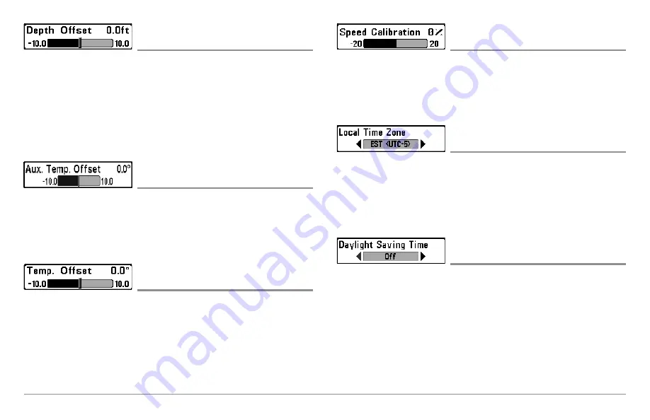
Depth Offset

(Advanced)

Settings:-10.0 to +10.0 feet or -3 to 3 meters
[International models only], Default = 0.0, or Off

Depth Offset

will adjust the digital depth readout to indicate depth from the

waterline or boats keel. Enter a positive vertical measurement from the
transducer to the waterline to read the depth from the waterline. Enter a
negative vertical measurement from the transducer to keel to read the depth
from the keel.

Aux. Temp Offset

(Advanced)

Settings: -10.0 to +10.0 degrees, Default = 0

Aux Temp Offset

will adjust the aux temperature readout (the temperature

on the optional-purchase temperature probe or Temp/Speed accessory) by
the amount entered.

Temp. Offset

(Advanced)

Settings: -10.0 to +10.0 degrees, Default = 0, or Off

Temp Offset

will adjust the temperature readout by the amount entered.

Speed Calibration

(Advanced, with Speed paddlewheel only)

Settings: -20% to +20%, Default = 0%

Speed Calibration

will adjust the speed readout by the percentage entered,

and will appear in the menu if a Speed accessory is connected and the
paddlewheel has moved at least once.

Local Time Zone

(Advanced)

Settings: Various; Default = EST [UTC-5] - Eastern
Standard Time

Local Time Zone

selects your time zone in reference to the time reported by

the GPS receiver when Time+Date is selected as a Digital Readout on the
Sonar View (see

Setup Menu Tab: Select Readouts

).

Daylight Saving Time

(Advanced)

Settings: Off, On; Default = Off

Daylight Saving Time

adjusts the time display to account for local Daylight

Saving Time when Time+Date is selected as a Digital Readout on the Sonar
View (see

Setup Menu Tab: Select Readouts

).

Selecting On adds one hour to the time display adjusted for your local time
zone. Selecting Off leaves the time display as adjusted for your local time
zone.

Содержание 858c Combo

Страница 1: ......

Страница 2: ...anty WARNING This product contains chemicals known to the State of California to cause cancer and or reproductive harm WARNING Do not travel at high speed with the unit cover installed Remove the unit...

Страница 3: ...Locking Down the Transducer Optional 23 858c 958c Inside the Hull Transducer Installation DualBeam PLUS Transducer XNT 9 20 T 858c and 958c only 24 Locating the transducer mounting location 24 Trial i...

Страница 4: ...at s on the Side Imaging Display 898c SI and 998c SI only 48 Understanding the Side Imaging Display 49 Side Imaging Frequencies and Coverage 50 For Best Performance 51 On the Water Interpretation 51 V...

Страница 5: ...3 Self Test 83 Accessory Test 84 GPS Diagnostic View 84 X Press Menu 85 Main Menu 85 Quick Tips for the Main Menu 86 Note for all Menu Settings 86 User Mode Normal or Advanced 87 Sonar X Press Menu 88...

Страница 6: ...t Name Most recently created waypoint 101 Snapshot and Recording X Press Menu Snapshot and Recording View only 102 Start Recording optional purchase MMC SD Card Snapshot and Recording View only 102 St...

Страница 7: ...with Temperature input 115 Down Imaging Beam Width Advanced 115 Navigation Menu Tab 116 Current Track 116 Saved Tracks 117 Waypoints 117 Routes 118 Chart Orientation 118 North Reference 118 Waypoint D...

Страница 8: ...nly 127 User Mode 127 Language International only 127 Triplog Reset with Speed input only 127 Restore Defaults 127 Select Readouts Advanced 128 Depth Offset Advanced 129 Aux Temp Offset Advanced 129 T...

Страница 9: ...al Only are only available on products sold outside of the U S by our authorized international distributors To obtain a list of authorized international distributors please visit our web site at hummi...

Страница 10: ......

Страница 11: ...ur Fishing System sends a sound wave signal and determines distance by measuring the time between the transmission of the sound wave and when the sound wave is reflected off of an object it then uses...

Страница 12: ...e noise better high speed performance and enhanced depth capability High Definition Side Imaging Sonar 898c SI and 998c SI only The 898c SI Combo and 998c SI Combo use Side Imaging sonar to provide a...

Страница 13: ...ottom hardness water conditions and transducer installation QuadraBeam PLUS Sonar optional purchase QuadraBeam PLUS transducer only Your Fishing System supports the optional purchase QuadraBeam PLUS t...

Страница 14: ...etween each received signal the GPS receiver determines its distance to each satellite With distances known the GPS receiver mathematically triangulates its own position With once per second updates t...

Страница 15: ...anced features such as WeatherSense SmartCast and the AS WX 1 Satellite Weather Receiver When an accessory is plugged into the Fishing System additional functions will be added to the menu system auto...

Страница 16: ...nsducer and GPS receiver cables should not be cut and care should be used not to damage the cable insulation Basic installation tasks that you must perform include Installing the control head choose g...

Страница 17: ...overhead mounting The chosen mounting area should allow for sufficient room so the control head can pivot through the full tilt range and allow for easy removal and installation NOTE You can drill th...

Страница 18: ...d then run the cables to your control head mounting location Do not cut any cabling except the power cable If your cables are too short extensions are available from your local dealer or online from h...

Страница 19: ...Phillips countersink wood screws Hand tighten only 7 Place the mounting bracket on the mounting surface aligned with the drilled holes and fill the mounting holes with marine grade silicone Insert the...

Страница 20: ...to the wrong slots If you don t have a cable for every hole in the insert install the blank plugs to protect the control head from the weather 1 2 Cables Routed Behind Mounting Bracket 3 Gimbal Bracke...

Страница 21: ...esired viewing angle and secure by tightening the gimbal knobs NOTE You may wish to dress the cabling with nylon wire ties in order to hold the cables together and create a cleaner assembly The Hummin...

Страница 22: ...important to read the instructions completely and understand the mounting guidelines before beginning installation 1a If a fuse terminal is available use crimp on type electrical connectors not inclu...

Страница 23: ...US transom mounted transducer use the procedures in this section There are several procedures you will have to perform in order to install a transom mounted transducer They are as follows Locate the t...

Страница 24: ...f the boat and in the immediate area of the propeller s Clockwise propellers create more turbulence on the port side On outboard or inboard outboard boats it is best to locate the transducer at least...

Страница 25: ...from port to starboard and from bow to stern by placing your level on the deck of the boat first in one direction then in the other 2 Hold the mounting bracket against the transom of the boat in the l...

Страница 26: ...sary 1a If you already know your transom angle refer to the chart below for the initial position to use to set the ratchets If your transom is angled at 14 degrees a common transom angle for many boat...

Страница 27: ...cer knuckle to form one continuous line on the assembly NOTE The ratchets are keyed make sure that the square teeth on each ratchet face the square teeth on the transducer knuckle and the triangular t...

Страница 28: ...racket transducer assembly with the drilled holes in the transom With a 5 16 socket driver mount the assembly to the transom using the two 10 1 long screws provided NOTE Make sure that the mounting sc...

Страница 29: ...behind the boat 9 Mark the correct position on the transom by tracing the silhouette of the transducer mounting bracket with a pencil or marker 10 Tighten the pivot bolt using the pivot screw and nut...

Страница 30: ...0 degrees in the bracket Allow enough slack in the cable for this movement It is best to route the cable to the side of the transducer so the transducer will not damage the cable during movement 2a If...

Страница 31: ...test before locking the transducer in place Testing should be performed with the boat in the water although you can initially confirm basic operation with the boat out of the water 1 Press POWER once...

Страница 32: ...o gain access to the mounting screws then re align the mounting bracket against the transom of the boat to match the traced silhouette Check the bracket position with the level again to make sure it i...

Страница 33: ...using a pencil or marker Unscrew and remove the mounting screws and the transducer assembly and set aside 2 Drill the fourth mounting hole using a 9 64 drill bit Use a marine grade silicone sealant t...

Страница 34: ...probe Call the Humminbird Customer Resource Center at 1 800 633 1468 for details or visit humminbird com for more information NOTE Your transducer may not look exactly like the transducer shown in th...

Страница 35: ...t will be detected once the transducer is placed in the hull 3 Place the transducer body face down at the identified mounting location inside the hull with the end that has the mounting knuckle pointe...

Страница 36: ...water from inside the hull and thoroughly dry the mounting surface If the surface is excessively rough it may be necessary to sand the area to create a smooth mounting surface 4 Slowly and thoroughly...

Страница 37: ...ructions are presented in this installation guide Each boat hull represents a unique set of requirements that should be evaluated prior to installation It is important to read the instructions complet...

Страница 38: ...t determine the best location on the transom to install the transducer Consider the following to find the best location It is very important to locate the transducer in an area which is relatively fre...

Страница 39: ...the boat 1 Remove the transducer mounting template from this manual See Appendix A for the Transducer Mounting Template 2 Hold the template on the transom of the boat in the location where the transdu...

Страница 40: ...he transducer pivot assembly to the bracket 1 Slide the assembled transducer into the metal bracket from the bottom aligning the large hole at the top of the bracket with the hole in the pivot 2 Inser...

Страница 41: ...vot bolt after initial use as the plastic may still be conforming to the pressure from the lock washers 3 Adjust the height of the assembly so the face of the transducer is 1 8 3 mm to 1 4 6 mm beneat...

Страница 42: ...the bracket if it strikes an object make sure there is sufficient cable slack to accommodate this motion It is best to route the cable to the side of the transducer so the cable will not be damaged by...

Страница 43: ...m for more information Test and Finish the Transducer Installation When you have installed both the control head the transducer and accessories and have routed all the cables you must perform a final...

Страница 44: ...at the desired speeds you are ready to lock down the transducer settings 5 Mark the transducer bracket location on the transom with a pencil then pop up the bracket to reveal the mounting screws Tight...

Страница 45: ...sions should not exceed 50 16 m NOTE Remember to caulk or seal screw holes and drilled holes as needed to protect your boat from water damage 2 Screw on the receiver base to the stem first making sure...

Страница 46: ...only NOTE If the mounting surface is thin and made of a lighter material a backing material may be needed below the mounting surface No Access Under Mounting Location Follow these steps to deck mount...

Страница 47: ...g the Cable and Check GPS Receiver Operation After installing a GPS receiver you should perform the following procedure to finish routing the GPS cable to the control head and to check to make sure th...

Страница 48: ...enu choices The System Status Self Test screen will appear NOTE If you wait too long the system will default to whichever menu mode happens to be highlighted and you will have to start again 2 Self Te...

Страница 49: ...ntrol head and save settings in advance for later use See Start Up Options Menu for more information What s on the Control Head Your Fishing System user interface is easy to use A combination of keys...

Страница 50: ...Use the 4 WAY Cursor Control key to select Light or Background and then use the LEFT or RIGHT Cursor key to change the settings Press EXIT to exit the Light and Background submenu NOTE Your control h...

Страница 51: ...recording icon and then press the RIGHT Cursor key to start recording playback Press the RIGHT or LEFT Cursor keys to control the speed of playback VIEW PRESET Keys The VIEW PRESET keys are used to sa...

Страница 52: ...y will capture the screen image and display an error saying that a GPS position fix is required to create a waypoint NOTE You must have an optional purchase MMC SD card installed for the screen snapsh...

Страница 53: ...p with a more detailed map of North America Domestic models or a detailed map of Europe and Southeast Asia including Australia and New Zealand International models You can also purchase MMC SD cards w...

Страница 54: ...ctions included with the PC Connect Cable to connect your Fishing System to your computer Export Navigation Data You can export all saved Tracks Waypoints and Routes from your Fishing System to an opt...

Страница 55: ...colors moving across the display at the same depth 8 Barometric Pressure Requires optional purchase WeatherSense Bait Ball 5 9 RTS Real Time Sonar Window 10 11 4 1 2 3 5 6 7 Second Sonar Return When t...

Страница 56: ...from the bottom structure and fish that are within the transducer beam The RTS Window plots the depth and intensity of a sonar return See Sonar Menu Tab Real Time Sonar RTS Window SwitchFire SwitchFi...

Страница 57: ...the boat moves the unit charts the changes in depth on the display to create a profile of the Bottom Contour The type of bottom can be determined from the return charted on the display A Hard Bottom s...

Страница 58: ...h of the water column show variations in the distance to the bottom as the boat passes over 2 Distance Distance traveled with Speed accessory or GPS Receiver 3 Average Speed Average speed reading with...

Страница 59: ...er on the display to form the image that you see The rows closest to the boat icon at the top of the view are the most recent sonar data The information is scrolled down the screen as new data drawn a...

Страница 60: ...er also provides DualBeam PLUS at 200 83 kHz Selecting 800 kHz produces the sharpest image while selecting 455 kHz provides greater bottom coverage area Side Imaging Beams are extremely narrow from fr...

Страница 61: ...gine or the trolling motor Minimize turning time and avoid wave action that induces large side to side rocking of the boat For example if there is a lot of wave activity try to move the boat so that i...

Страница 62: ...erged Bridge 1 1 Submerged Standing and Fallen Timber and Bait Fish 1 Bait fish 1 Standing and fallen timber 2 2 Submerged Ravine with Timber Possible drop off 1 1 Submerged Bridge A Closer Perspectiv...

Страница 63: ...attached to your control head Side Imaging and Down Imaging Views are only available in the 898c SI and 998c SI Combo units and Side Beam View is only available when an optional purchase QuadraBeam PL...

Страница 64: ...ET keys for several seconds A chime will indicate that the view has been saved You can store up to three views one on each key To change the Digital Readouts Each view displays digital readout informa...

Страница 65: ...Display for more information Freeze Frame Press any arrow on the 4 WAY Cursor Control key and the SI View will freeze and a cursor will appear on the screen Use the 4 WAY Cursor Control key to move th...

Страница 66: ...nu Tab Down Imaging Beam Width Down Imaging X Press Menu Press the MENU key once to access the Down Imaging X Press Menu You can set the sensitivity of the sonar to see more or less detail the chart s...

Страница 67: ...ings or the optional purchase accessories attached see Setup Menu Tab Select Readouts Freeze Frame Use the 4 WAY Cursor Control key to freeze the display and move the cursor over a sonar return The de...

Страница 68: ...om Preview Box which shows where the zoomed view is in relation to the full range view The Upper and Lower Depth Range numbers indicate the high and low range of the water which is being viewed Digita...

Страница 69: ...corner The Digital Readouts in the Split Sonar View cannot be customized therefore information such as water temperature and voltage are unavailable in the Split Sonar View Freeze Frame Use the 4 WAY...

Страница 70: ...Menu Press the MENU key once in this view to open the X Press Menu Use the X Press Menu to Start Recording Delete Images or adjust the Recording and Playback settings see Recording and Playback or Sn...

Страница 71: ...pshot and Recording View press the UP or DOWN Cursor keys to scroll through the saved files and highlight a snapshot file 2 Press the Menu key once and select Delete Image from the X Press Menu 3 Pres...

Страница 72: ...required for viewing the screen snapshots from your control head so don t delete these files Recording and Playback The Recording feature records active sonar information When the recording is played...

Страница 73: ...NU key once to open the Snapshot and Recording X Press Menu 2 Use the X Press Menu to adjust the Sonar Recording s Sensitivity Upper Range Lower Range and the Playback Speed See Snapshot and Recording...

Страница 74: ...depth and information for the location you choose Press Exit to resume Playback Press the MARK key during Playback to save a Screen Snapshot and or mark a waypoint in the view or active cursor locati...

Страница 75: ...y the Lower Range setting for the down looking beam up to a maximum of 160 feet see Sonar X Press Menu Lower Range Layout The Side Beam View can be arranged in any of the following layouts Default Cla...

Страница 76: ...beams and the 200 kHz down looking sonar beam as three panels of historical data This layout is presented as three slanted panels New information appears on the right and scrolls to the left Side Beam...

Страница 77: ...en behind the boat Press the RIGHT or LEFT Cursor keys to turn the eye point right or left Press the UP Cursor key to move the eye point forward and press the DOWN Cursor key to move the eye point bac...

Страница 78: ...hen navigating are overlaid on the chart Use the 4 WAY Cursor Control key to shift pan the chart to another area Press the ZOOM keys to zoom in and out Press the INFO key to get information about the...

Страница 79: ...ress the MENU key once to access the X Press Menu The X Press Menu provides settings for the active view and the display updates immediately with your changes Display Size Press the MENU key once and...

Страница 80: ...9 Latitude and Longitude Position of Cursor 1 6 Distance to the Cursor 7 8 9 10 11 2 3 4 5 Bearing to the Cursor Cartography Active Cursor Chart Window 2 Track Breadcrumb Trail Boat Icon Chart Window...

Страница 81: ...een Chart Side Combo View Depth Topography Changes 1 7 Bottom Return 8 Water Surface Temperature Chart View Window 3 9 Speed of Boat Boat Icon 4 10 Side Imaging View Window Cartography 5 11 Shadows 6...

Страница 82: ...creen Chart Down Imaging Combo View Digital Readouts Chart View Window 1 7 Green Arrow Active Side 8 Upper Depth Range Cartography 3 9 Depth Lines Map Scale 4 10 Bottom Return Boat Icon 5 11 Shadows 6...

Страница 83: ...left side of the screen and Side Imaging on the right side of the screen If you use the active cursor on the left side of the screen a cursor will appear in both the Sonar and Down Imaging views Down...

Страница 84: ...d in the direction of motion always Up in the Course Up orientation Viewing Cartography In the Chart and Combo Views there are several cartography related functions that you can access using various k...

Страница 85: ...ormation box and the cursor bull s eye will be centered over the port position The cursor information boxes will indicate the distance and bearing to the port from your present position Nearest Tide S...

Страница 86: ...b trail of trackpoints The Current Track shows the position history since the unit was powered up maximum of 20 000 trackpoints displayed You can clear the Current Track or save it at any time Your Fi...

Страница 87: ...t a waypoint From the Waypoints submenu select Edit and press the RIGHT Cursor key to display the saved waypoints list Select the waypoint you want to edit and press the RIGHT Cursor key Use the 4 WAY...

Страница 88: ...move any saved routes from memory You will be prompted to save the current route when you cancel navigation Add a Waypoint Target or Trolling Grid The Waypoint Target shows a target consisting of conc...

Страница 89: ...dialog box highlight a waypoint in the In Route list and press the RIGHT Cursor key to access the Waypoint In Route submenu From this submenu you can move the waypoint up or down in the route order or...

Страница 90: ...ack From the Saved Tracks submenu select Edit and press the RIGHT Cursor key to display the saved tracks list Select the track you want to edit and press the RIGHT Cursor key Delete a saved track From...

Страница 91: ...ew will switch to the Chart View and the elapsed time since MOB was activated will be displayed A line will be drawn from the boat s current position to the MOB waypoint and the MOB waypoint will be t...

Страница 92: ...r the following tabbed headings Alarms Sonar Navigation Chart Setup Views and Accessories NOTE The X Press Menu s and the Main Menu options can also be expanded or simplified by setting the User Mode...

Страница 93: ...r Fishfinder NOTE It is important to select Simulator manually from the Start Up Options Menu as opposed to letting the Fishfinder enter Simulator automatically as it will if a transducer is not conne...

Страница 94: ...ing monitored but is not yet being used This view also reports the current position local time and date and other numeric information The current GPS Fix Type is reported as No Fix 2D Fix 3D Fix or En...

Страница 95: ...provides the standard set of menu options including the settings that are changed less frequently The Main Menu is organized under the following tabs to help you find a specific menu item quickly Ala...

Страница 96: ...the Main Menu at a later time the menu will open to the same tab as the last time the Main Menu was displayed Note for all Menu Settings The settings in all menus are adjusted in the same way Simply...

Страница 97: ...tting 1 Press the MENU key twice to access the Main Menu 2 Press the RIGHT Cursor key until the Setup tab is selected 3 Press the DOWN Cursor key to highlight User Mode on the Setup main menu 4 Press...

Страница 98: ...n active side you can apply menu settings and key commands to the view you ve selected The Active Side menu option is only available when a Combo View is on the screen see Views Combo Views A green ar...

Страница 99: ...sonar frequencies Upper Range Advanced Sonar Split Sonar and Active Sonar Side Views only Settings 0 to 1490 or 0 to 497 meters International models only Default 0 Upper Range sets the shallowest dept...

Страница 100: ...speed keeps the information on the display longer but the bottom and fish details become compressed and may be difficult to interpret Regardless of the Chart Speed setting the RTS Window will update...

Страница 101: ...ows you to control how much of the water column measured up from the bottom is shown in the Sonar Zoom View Choose a small value to see low lying bottom structure or details of the bottom return Choos...

Страница 102: ...enu settings and key commands to the view you ve selected The Active Side menu option is only available when a Combo View is on the screen see Views Combo Views A green arrow on the Combo View points...

Страница 103: ...itivity Contrast and Sharpness Whether you re searching the Side Imaging data for fish or certain bottom contour the most effective settings will vary with the situation The display will update as you...

Страница 104: ...d shows more information in the Side Imaging Views and is preferred by most anglers however the sonar information moves across the display quickly A slower speed keeps the information on the display l...

Страница 105: ...enu settings and key commands to the view you ve selected The Active Side menu option is only available when a Combo View is on the screen see Views Combo Views A green arrow on the Combo View points...

Страница 106: ...tivity is adjusted too low the display may not show many sonar returns that could be fish Upper Range Advanced Down Imaging Views only Settings 0 to 1490 or 0 to 497 meters International models only D...

Страница 107: ...ail shown A faster speed shows more information and is preferred by most anglers however the sonar information moves across the display quickly A slower speed keeps the information on the display long...

Страница 108: ...se an active side you can apply menu settings and key commands to the view you ve selected The Active Side menu option is only available when a Combo View is on the screen see Views Combo Views A gree...

Страница 109: ...g grid to a waypoint selected from the saved waypoints list Cursor to Waypoint Chart or Combo View only Settings Press the RIGHT Cursor key and follow screen instructions Cursor to Waypoint allows you...

Страница 110: ...not delete a previously saved route Cancel MOB Navigation only when MOB Navigation is activated Settings Press the RIGHT Cursor key and follow screen instructions Cancel MOB Navigation removes the Ma...

Страница 111: ...oint Submenu contains the following menu options Edit allows you to edit the Name Position Latitude and Longitude and select the Icon that will be used to represent the waypoint in the Chart and Combo...

Страница 112: ...menu option is only available when an optional purchase MMC SD card is installed and Snapshot and Recording View is on the screen Stop Recording optional purchase MMC SD Card only Settings Press the R...

Страница 113: ...purchase MMC SD card is installed and Snapshot and Recording View is on the screen Pings Per Second optional purchase MMC SD Card Snapshot and Recording View only Settings 1 10 AUTO Default AUTO Ping...

Страница 114: ...nar return can be processed Stop Playback optional purchase MMC SD Card only Settings Press the RIGHT Cursor key to activate Stop Playback allows you to stop playback of a sonar recording from any vie...

Страница 115: ...nly Default OFF Depth Alarm sounds when the depth becomes equal to or less than the menu setting Fish ID Alarm Settings Off All Large Medium Large Default Off Fish ID Alarm sounds when the Fishfinder...

Страница 116: ...hfinder reaches the Temp Alarm setting which is either set in degrees Fahrenheit or Celsius International Models only Off Course Alarm Settings Off 25 to 3000 ft 10 to 1000 m International Models only...

Страница 117: ...re the Arrival Alarm will sound Drift Alarm Settings Off 25 to 3000 ft 10 to 1000 m International Models only Default Off Drift Alarm allows you to set the size of a perimeter around the boat s anchor...

Страница 118: ...isplay the sonar returns from each beam in their respective windows The blended information is shown in the Sonar View The RTS Window in the Sonar View will only show the returns from the 200 kHz narr...

Страница 119: ...r Mode Max Mode Default Clear Mode SwitchFire controls how the sonar returns are displayed in the Sonar Views Choose Max Mode to see only raw sonar returns on the display When Max Mode is selected you...

Страница 120: ...Due to the transducer beam angle the distance to a fish decreases as the fish moves into the beam and then increases as it moves out again creating a Fish Arch when this distance change is shown on t...

Страница 121: ...lette Palette 1 Palette 2 Palette 3 Default Original Sonar Colors allows you to select which color palette you would like to use for the display Gray Green Inverse where white strong returns and black...

Страница 122: ...0 kHz sonar window 455 kHz Sensitivity Advanced with optional purchase QuadraBeam PLUS transducer Settings 10 to 10 Default 0 455 kHz Sensitivity adjusts the sensitivity of the 455 kHz beam Increase t...

Страница 123: ...m High1 High2 High3 Default Low Noise Filter adjusts the sonar Noise Filter to limit interference on the display from sources such as your boat engine turbulence or other sonar devices The Off setting...

Страница 124: ...llow or deep setting Water Type affects the accuracy of deep water depth readings In salt water what would be considered a large fish might be 2 to 10 times bigger than a large fish in fresh water dep...

Страница 125: ...temperature graph over the main Sonar View to show temperature changes correlated to recent sonar history Down Imaging Beam Width Advanced Settings Narrow Medium Wide Default Wide Down Imaging Beam Wi...

Страница 126: ...rent Track Submenu contains the following menu options Save allows you to save the current track Clear allows you to delete the current track Appearance allows you to change the style and color of the...

Страница 127: ...on The icon used to represent the waypoint in the Chart and Combo Views can also be changed Edit allows you to choose from the saved waypoints list and then edit the Name and Position Latitude and Lon...

Страница 128: ...immediately Info provides information about the route you choose from the saved routes list including the distance and bearing from each waypoint to the next Chart Orientation Settings North Up Cours...

Страница 129: ...to the current track During slow travel or drift setting both Trackpoint Interval and Track Min Distance to small values will allow you to increase the track resolution Track Min Distance Advanced Set...

Страница 130: ...and Routes to an MMC SD card If an MMC card isn t installed an error message will be displayed Insert the MMC card and try again See Multi Media Card MMC SD Slots for more information Delete All Nav...

Страница 131: ...ontour XD Left Chart Card Right Chart Card Default Auto Chart Select allows you to choose which chart to use if you have built in charts or a map card If you select Auto your unit will select a chart...

Страница 132: ...offset used by your Fishfinder Press the 4 WAY Cursor Control key to activate the cursor and move it to the location where the Map Offset will be applied Then confirm the map offset position using the...

Страница 133: ...formation All shows roads buildings railways and other notations in addition to the Basic Navigation and Underwater information Map Borders Settings Hidden MMC SD Only All Visible Default MMC SD Only...

Страница 134: ...depth you set will be highlighted in green Use Depth Highlight with Depth Highlight Range Depth Highlight Range optional purchase LakeMaster charts only Settings 0 60 ft 0 30 fathoms 0 20 m Internati...

Страница 135: ...t option for the list Scroll Use the UP or DOWN Cursor keys to scroll through the list As each lake is highlighted you can view information about the lake in the white box displayed on the screen Curs...

Страница 136: ...he units of measure for all depth related readouts Units Temp International only Settings Celsius Fahrenheit Default Celsius Units Temp selects the units of measure for all temperature related readout...

Страница 137: ...et to Advanced default setting additional menu options are added to the menu system See Main Menu User Mode for details Language International only Settings Various Default English Language selects th...

Страница 138: ...4 Split Cross Track Error XTE and Distance To Go DTG and Readout 5 Split Time To Go TTG and Speed Chart Views Readouts 1 3 and 4 can be customized Readout 2 Heading and Readout 5 Speed are fixed and...

Страница 139: ...e readout by the amount entered Speed Calibration Advanced with Speed paddlewheel only Settings 20 to 20 Default 0 Speed Calibration will adjust the speed readout by the percentage entered and will ap...

Страница 140: ...isplay when Time Date is selected as a Digital Readout on the Sonar View see Setup Menu Tab Select Readouts Digits Format Advanced Settings Small tenths Large tenths No tenths Default Small tenths Dig...

Страница 141: ...visible or off The Demonstration Mode appears on the screen if you don t press any keys during the warning screen at power up Menu settings cannot be saved in Demonstration see Power On the Control H...

Страница 142: ...Accessories tab is selected Screen Snapshot will always appear under the Accessories tab If you attach additional accessories to the control head the menu choices that support the accessory will be ad...

Страница 143: ...rcle with a slanted line through it on the Snapshot and Recording View on the other unit AIS optional purchase AIS equipment only Settings Press the RIGHT Cursor key to activate Your Fishing system is...

Страница 144: ...I Tag Maritime Mobile Service Identity will be displayed if it is available for each target Target Course Lines point in the direction of a vessel s course The length of the line can be adjusted in th...

Страница 145: ...vailable with each AIS update Press the RIGHT Cursor key to open the Target List Sort The list is sorted by MMSI number if available Targets without an MMSI will be shown at the bottom of the list Scr...

Страница 146: ...battery terminals or wiring or actually replacing the battery if necessary Fishing System Defaults to Simulator with a Transducer Attached A connected and functioning transducer will cause the newly s...

Страница 147: ...air and water flowing around the transducer cavitation may be interfering with the interpretation of sonar data See your Installation Guide for suggestions on adjusting the transducer position Electr...

Страница 148: ...To determine whether the boat s engine is the source of the noise increase the RPMs while the boat is in neutral and stationary to see if the noise increases proportionately if noise appears when you...

Страница 149: ...BE THE CUSTOMER S EXCLUSIVE REMEDY EXCEPT FOR ANY APPLICABLE IMPLIED WARRANTIES UNDER STATE LAW WHICH ARE HEREBY LIMITED IN DURATION TO ONE YEAR FROM THE DATE OF ORIGINAL PURCHASE IN NO EVENT WILL HUM...

Страница 150: ...r your e mail subject header You should include your Repair Authorization Number in all subsequent communications about your unit For IN WARRANTY service complete the following steps Obtain a Repair A...

Страница 151: ...e Fishing System PC Connect Cable Purchase the PC Connect Cable to connect the Fishing System to a PC in order to upload product software updates and new features obtained from humminbird com This acc...

Страница 152: ...our web site humminbird com for additional new and exciting accessories to grow your Fishing System NOTE Each accessory requires a separate purchase You can visit our web site at humminbird com or co...

Страница 153: ...distributor from which your product was purchased ROHS STATEMENT Product designed and intended as a fixed installation or part of a system in a vessel may be considered beyond the scope of Directive 2...

Страница 154: ...monochrome fixed mount Humminbird products use FSTN technology Frequency A measure of the number of sound wave cycles per second of a sound impulse transmitted underwater A typical frequency for fish...

Страница 155: ...st effective tool Sonar is the basic technology behind all recreational and commercial fishfinding and depthfinding devices Sonar Update Rate The number of times per second that the transducer s trans...

Страница 156: ...s flattens out the bottom contour but is effective at showing fish on or near the bottom and is preferred by many saltwater anglers Acquisition Time The length of time that a GPS receiver typically ta...

Страница 157: ...nformation MMC is a very rugged format suitable for the marine environment but it is not waterproof MMC is the same format that many digital cameras use See SD North Magnetic The principle reference p...

Страница 158: ...etween two waypoints and it represents the most efficient path between the two points because it is a straight line The TRK is measured in degrees i e 321 where 000 is North 090 East 180 is South 270...

Страница 159: ...149 Appendix A Side Imaging Transducer Mounting Template XHS 9 HDSI 180 T Appendix A...

Страница 160: ...ys By Telephone Monday Friday 8 00 a m to 4 30 p m Central Standard Time 1 800 633 1468 By e mail typically we respond to your e mail within three business days service humminbird com For direct shipp...

Отзывы: