lp-445-r4 Rev. 006 Rel. 027 Date 7.21.20
29
NOTE:
Check with your local gas company to determine if
combustion condensate disposal is permitted in your area. In the
state of Massachusetts, condensate must be neutralized before
entering a drain.
This boiler is a high efficiency appliance, and therefore produces
condensate: a by-product of the combustion process. A condensate
collection system with an internal float switch monitors condensate
level to prevent it from backing up into the combustion system.
There is a ¾” sweat connection provided to connect the outlet of the
collection system to a drain or condensate pump.
Condensate from the boiler is slightly acidic with a pH of 3.2 - 4.5.
To avoid long term damage to the drainage system and to meet
local code requirements, HTP recommends neutralizing condensate
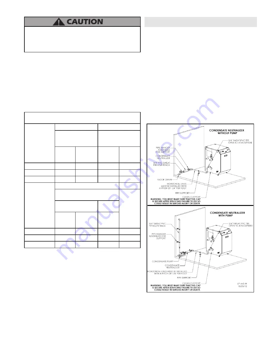
with a Condensate Neutralizer Kit (Part # 7350P-611). The neutralizer
kit connects to the drain system and contains limestone chips
that neutralize the pH level of the condensate. The neutralizer kit
should be checked annually and the limestone chips replenished if
necessary. When replacing the limestone chips, take care to ensure
chips are no smaller than ½” to avoid blockage in condensate piping
(refer to figure below for piping of the condensate neutralizer.)
Figure 21 - Condensate Piping
NOTES:
1. Condensate line must be pitched at least ¼” per foot to properly
drain. If this cannot be done, or a very long length of condensate
hose is used, increase the condensate line to a minimum of 1” ID and
place a tee in the line after the condensate neutralizer to properly
reduce vacuum lock in the drain line.
2. PVC or CPVC pipe should be the only material used for condensate
line. Steel, brass, copper, and other metals will be subject to corrosion
Under no circumstances should the mechanical room ever be under
negative pressure. Particular care should be taken where exhaust
fans, attic fans, clothes dryers, compressors, air handling units, etc.,
may take away air from the unit. Failure to follow these instructions
could result in property damage or personal injury.
Combustion air supply must be completely free of any flammable
vapors that may ignite, or chemical fumes which may be corrosive to
the boiler. See Table 1 for a list of combustion air contaminants. These
chemicals, when burned, form acids which quickly attack the stainless
steel heat exchanger, headers, flue connectors, and the vent system.
The result is improper combustion and premature boiler failure. Such
failure IS NOT covered under warranty.
EXHAUST FANS:
Any fan or appliance which exhausts air from the
mechanical room may deplete the combustion air supply and/or
cause a downdraft in the venting system. Spillage of flue products
from the venting system into an occupied living space can cause a very
hazardous condition that must be corrected immediately.
Minimum Recommended Combustion Air Supply to Mechanical
Room
Model
Figure 17
Figure 18
*Outside Air from 2
Openings Directly from
Outdoors
1
*Outside Air from 2
Ducts Delivered from
Outdoors
1
Top
Opening,
in
2
Bottom
Opening,
in
2
Top
Opening,
in
2
Bottom
Opening,
in
2
500
125
125
250
250
700
175
175
350
350
850
215
215
425
425
Model
Figure 19
Figure 20
Inside Air from 2 Ducts Delivered
from Interior Space
2
*Outside
Air from 1
Opening
Directly
from
Outdoors,
in
2 1
Same Story
Different
Stories
Top
Opening,
in
2
Bottom
Opening,
in
2
Top
Opening,
in
2
500
500
500
1000
170
700
700
700
1400
235
850
850
850
1700
285
Table 13 - Indoor Combustion Air Sizing
The above requirements are for the boiler only; additional gas fired
appliances in the mechanical room will require an increase in the net
free area and/or volume to supply adequate combustion air for all
appliances.
No combustion air openings are needed when the boiler is installed
in a space with a volume NO LESS than 50 cubic feet per 1,000 BTU/hr
of all installed gas fired appliances. Buildings MUST NOT be of *”Tight
Construction”.
1
Outside air openings shall communicate with the outdoors.
2
Combined interior space must be 50 cubic feet per 1,000 BTU/hr
input. Buildings MUST NOT be of *”Tight Construction”.
Part 6 - Condensate Removal
Содержание MODCON500 FS
Страница 34: ...lp 445 r4 Rev 006 Rel 027 Date 7 21 20 34 Figure 26 Cascade Master and Follower Wiring ...
Страница 61: ...lp 445 r4 Rev 006 Rel 027 Date 7 21 20 61 Figure 34 Water Side Replacement Parts All Models ...
Страница 62: ...lp 445 r4 Rev 006 Rel 027 Date 7 21 20 62 Figure 35 Cabinet Replacement Parts All Models See Table ...
Страница 65: ...lp 445 r4 Rev 006 Rel 027 Date 7 21 20 65 Maintenance Notes ...


