Hardware options installation 28
7.
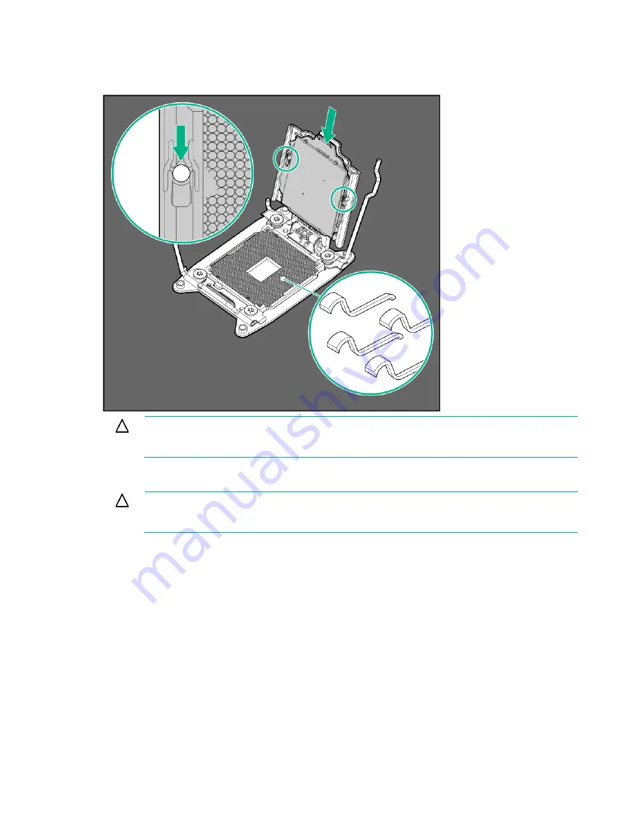
Install the processor. Verify that the processor is fully seated in the processor retaining bracket by
visually inspecting the processor installation guides on either side of the processor.
THE PINS ON
THE SYSTEM BOARD ARE VERY FRAGILE AND EASILY DAMAGED.
CAUTION:
THE PINS ON THE SYSTEM BOARD ARE VERY FRAGILE AND EASILY
DAMAGED.
To avoid damage to the system board, do not touch the processor or the
processor socket contacts.
8.
Close the processor retaining bracket. When the processor is installed properly inside the processor
retaining bracket, the processor retaining bracket clears the flange on the front of the socket.
CAUTION:
Do not press down on the processor. Pressing down on the processor may cause
damage to the processor socket and the system board. Press only in the area indicated on the
processor retaining bracket.
Содержание ProLiant SL270s Gen8
Страница 16: ...Operations 16 5 Remove the shipping plates 6 Remove the hard drive cage...
Страница 17: ...Operations 17 7 Loosen screws securing the GPU shelf 8 Remove the GPU shelf...
Страница 18: ...Operations 18 9 Remove the processor air baffle To replace the component reverse the removal procedure...
Страница 36: ...Hardware options installation 36 5 Remove the shipping plates 6 Remove the hard drive cage...
Страница 42: ...Hardware options installation 42 6 Remove the hard drive cage 7 Loosen screws securing the GPU shelf...
Страница 45: ...Hardware options installation 45 7 Remove the hard drive cage 8 Loosen screws securing the GPU shelf...
Страница 47: ...Hardware options installation 47 o Left node o Right node...
Страница 49: ...Hardware options installation 49 5 Remove the shipping plates 6 Remove the hard drive cage...
Страница 50: ...Hardware options installation 50 7 Loosen screws securing the GPU shelf 8 Remove the GPU shelf...
Страница 53: ...Hardware options installation 53 4 Remove all shipping brackets 5 Remove the shipping plates...
Страница 54: ...Hardware options installation 54 6 Remove the hard drive cage 7 Loosen screws securing the GPU shelf...
Страница 55: ...Hardware options installation 55 8 Remove the GPU shelf 9 Remove the PCI cage...
Страница 59: ...Hardware options installation 59 5 Remove the shipping plates 6 Remove the hard drive cage...
Страница 60: ...Hardware options installation 60 7 Loosen screws securing the GPU shelf 8 Remove the GPU shelf...
Страница 61: ...Hardware options installation 61 9 Remove the PCI cage 10 Install the riser card into the PCI cage...
Страница 67: ...Hardware options installation 67 6 Remove the hard drive cage 7 Loosen screws securing the GPU shelf...
Страница 72: ...Cabling 72 Right node Capacitor pack to FBWC on controller card cabling o Left node...
Страница 73: ...Cabling 73 o Right node...
Страница 97: ...Support and other resources 97...
Страница 98: ...Support and other resources 98...
Страница 106: ...Index 106 V ventilation 19 W warnings 21 website Hewlett Packard Enterprise 91...


