Hardware options installation 35
Lockstep Memory population guidelines
For Lockstep memory mode configurations, observe the following guidelines:
•
Observe the general DIMM slot population guidelines (on page
•
DIMM configuration on all channels of a processor must be identical.
•
In multi-processor configurations, each processor must have a valid Lockstep Memory configuration.
•
In multi-processor configurations, each processor may have a different valid Lockstep Memory
configuration.
Population order
For memory configurations with a single processor or multiple processors, populate the DIMM
sequentially in alphabetical order (A through H).
After installing the DIMMs, use RBSU to configure Advanced ECC, online spare, or lockstep memory
support.
Installing a DIMM
CAUTION:
To avoid damage to the drives, memory, and other system components, the air
baffle, and drive blanks must be installed when the server is powered up.
1.
Power down the server (on page
2.
Disconnect all peripheral cables from the server.
3.
Remove the server from the chassis (on page
4.
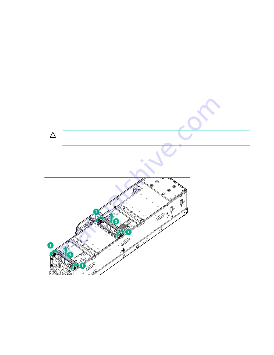
Remove all shipping brackets.
Содержание ProLiant SL270s Gen8
Страница 16: ...Operations 16 5 Remove the shipping plates 6 Remove the hard drive cage...
Страница 17: ...Operations 17 7 Loosen screws securing the GPU shelf 8 Remove the GPU shelf...
Страница 18: ...Operations 18 9 Remove the processor air baffle To replace the component reverse the removal procedure...
Страница 36: ...Hardware options installation 36 5 Remove the shipping plates 6 Remove the hard drive cage...
Страница 42: ...Hardware options installation 42 6 Remove the hard drive cage 7 Loosen screws securing the GPU shelf...
Страница 45: ...Hardware options installation 45 7 Remove the hard drive cage 8 Loosen screws securing the GPU shelf...
Страница 47: ...Hardware options installation 47 o Left node o Right node...
Страница 49: ...Hardware options installation 49 5 Remove the shipping plates 6 Remove the hard drive cage...
Страница 50: ...Hardware options installation 50 7 Loosen screws securing the GPU shelf 8 Remove the GPU shelf...
Страница 53: ...Hardware options installation 53 4 Remove all shipping brackets 5 Remove the shipping plates...
Страница 54: ...Hardware options installation 54 6 Remove the hard drive cage 7 Loosen screws securing the GPU shelf...
Страница 55: ...Hardware options installation 55 8 Remove the GPU shelf 9 Remove the PCI cage...
Страница 59: ...Hardware options installation 59 5 Remove the shipping plates 6 Remove the hard drive cage...
Страница 60: ...Hardware options installation 60 7 Loosen screws securing the GPU shelf 8 Remove the GPU shelf...
Страница 61: ...Hardware options installation 61 9 Remove the PCI cage 10 Install the riser card into the PCI cage...
Страница 67: ...Hardware options installation 67 6 Remove the hard drive cage 7 Loosen screws securing the GPU shelf...
Страница 72: ...Cabling 72 Right node Capacitor pack to FBWC on controller card cabling o Left node...
Страница 73: ...Cabling 73 o Right node...
Страница 97: ...Support and other resources 97...
Страница 98: ...Support and other resources 98...
Страница 106: ...Index 106 V ventilation 19 W warnings 21 website Hewlett Packard Enterprise 91...


