Hardware options installation 69
10.
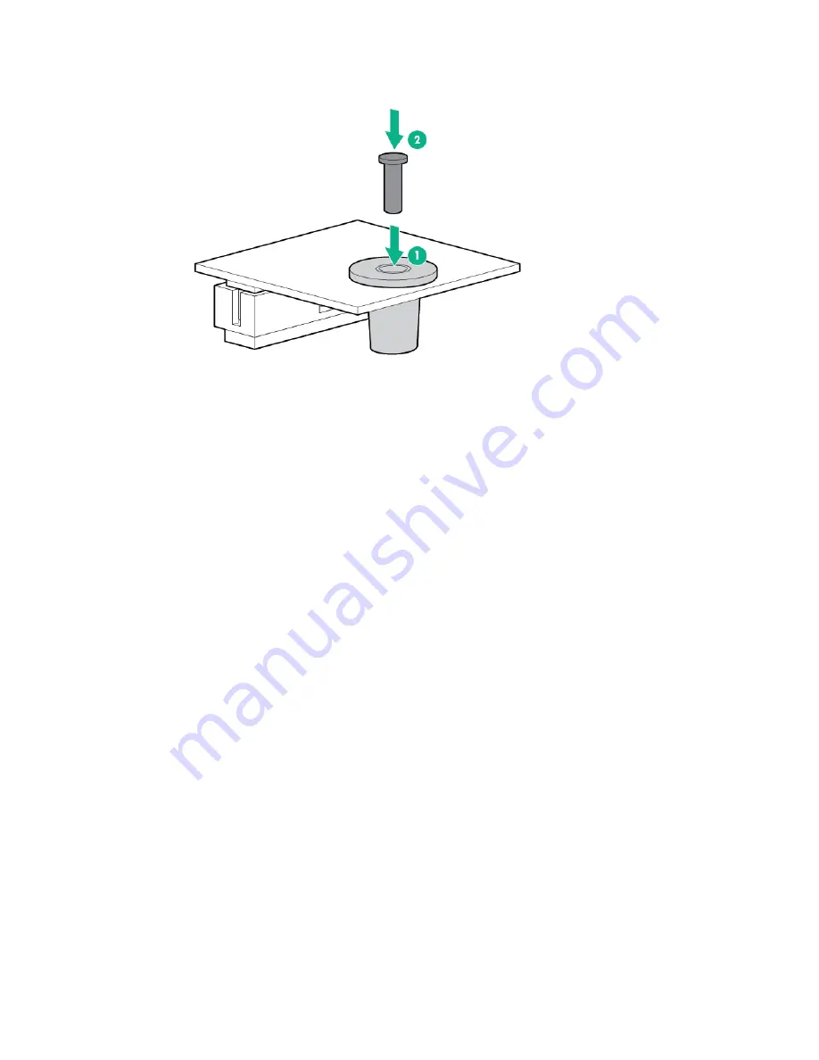
Install the TPM security rivet by pressing the rivet firmly into the system board.
11.
Install the GPU cage
12.
Install the SFF hot-plug drive cage.
13.
Install the shipping brackets and shipping plates.
14.
Install the server into the chassis ("
Installing the server into the chassis
" on page
15.
Connect the peripheral cables.
16.
Power up the server (on page
Retaining the recovery key/password
The recovery key/password is generated during BitLocker setup, and can be saved and printed after
BitLocker is enabled. When using BitLocker, always retain the recovery key/password. The recovery
key/password is required to enter Recovery Mode after BitLocker detects a possible compromise of
system integrity.
To help ensure maximum security, observe the following guidelines when retaining the recovery
key/password:
•
Always store the recovery key/password in multiple locations.
•
Always store copies of the recovery key/password away from the server.
•
Do not save the recovery key/password on the encrypted hard drive.
Enabling the Trusted Platform Module
1.
When prompted during the start-up sequence, access RBSU by pressing the
F9
key.
2.
From the Main Menu, select
Server Security
.
3.
From the Server Security Menu, select
Trusted Platform Module
.
4.
From the Trusted Platform Module Menu, select
TPM Functionality
.
5.
Select
Enable
, and then press the
Enter
key to modify the TPM Functionality setting.
6.
Press the
Esc
key to exit the current menu, or press the
F10
key to exit RBSU.
7.
Reboot the server.
8.
Enable the TPM in the OS. For OS-specific instructions, see the OS documentation.
Содержание ProLiant SL270s Gen8
Страница 16: ...Operations 16 5 Remove the shipping plates 6 Remove the hard drive cage...
Страница 17: ...Operations 17 7 Loosen screws securing the GPU shelf 8 Remove the GPU shelf...
Страница 18: ...Operations 18 9 Remove the processor air baffle To replace the component reverse the removal procedure...
Страница 36: ...Hardware options installation 36 5 Remove the shipping plates 6 Remove the hard drive cage...
Страница 42: ...Hardware options installation 42 6 Remove the hard drive cage 7 Loosen screws securing the GPU shelf...
Страница 45: ...Hardware options installation 45 7 Remove the hard drive cage 8 Loosen screws securing the GPU shelf...
Страница 47: ...Hardware options installation 47 o Left node o Right node...
Страница 49: ...Hardware options installation 49 5 Remove the shipping plates 6 Remove the hard drive cage...
Страница 50: ...Hardware options installation 50 7 Loosen screws securing the GPU shelf 8 Remove the GPU shelf...
Страница 53: ...Hardware options installation 53 4 Remove all shipping brackets 5 Remove the shipping plates...
Страница 54: ...Hardware options installation 54 6 Remove the hard drive cage 7 Loosen screws securing the GPU shelf...
Страница 55: ...Hardware options installation 55 8 Remove the GPU shelf 9 Remove the PCI cage...
Страница 59: ...Hardware options installation 59 5 Remove the shipping plates 6 Remove the hard drive cage...
Страница 60: ...Hardware options installation 60 7 Loosen screws securing the GPU shelf 8 Remove the GPU shelf...
Страница 61: ...Hardware options installation 61 9 Remove the PCI cage 10 Install the riser card into the PCI cage...
Страница 67: ...Hardware options installation 67 6 Remove the hard drive cage 7 Loosen screws securing the GPU shelf...
Страница 72: ...Cabling 72 Right node Capacitor pack to FBWC on controller card cabling o Left node...
Страница 73: ...Cabling 73 o Right node...
Страница 97: ...Support and other resources 97...
Страница 98: ...Support and other resources 98...
Страница 106: ...Index 106 V ventilation 19 W warnings 21 website Hewlett Packard Enterprise 91...


