4
.
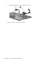
Remove the top cover trim from the computer. The top cover trim is included in the Door/Cover Kit,
spare part number 417073-001.
5
.
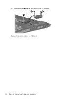
Disconnect the display switch module cable
(1)
from the system board.
6
.
Remove the Phillips PM2.0×3.0 screw
(2)
that secures the display switch module to the computer.
7
.
Remove the display switch module
(3)
from the computer.
Reverse this procedure to install the display switch module.
90 Chapter
4
Removal and replacement procedures
Содержание PAVILION DV2500
Страница 1: ...HP Pavilion dv2500 Notebook PC Maintenance and Service Guide ...
Страница 4: ...iv Safety warning notice ...
Страница 145: ...Where used One screw that secures the connector bracket to the computer Silver Phillips PM2 5 5 0 screw 137 ...
Страница 172: ......


