background image

4-18

Using the HP Web Browser Interface

Status Reporting Features

Us

in

g t

h

e HP

 Web

 Bro

w

ser


In

te

rf

a

c

e

Maximum Activity Indicator:

 As the bars in the graph area change 

height to reflect the level of network activity on the corresponding port, 
they leave an outline to identify the maximum activity level that has been 
observed on the port.

Utilization Guideline.  

A network utilization of 40% is considered the 

maximum that a typical Ethernet-type network can experience before encoun-
tering performance difficulties. If you observe utilization that is consistently 
higher than 40% on any port, click on the Port Counters button to get a detailed 
set of counters for the port.

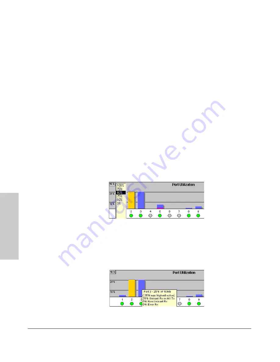
To change the amount of bandwidth the Port Utilization bar graph 
shows.  

 Click on the bandwidth display control button in the upper left corner 

of the graph. (The button shows the current scale setting, such as 40%.) In the 
resulting menu, select the bandwidth scale you want the graph to show (3%, 
10%, 25%, 40%, 75%, or 100%), as shown in figure 3-7.

Note that when viewing activity on a gigabit port, you may want to select a 
lower value (such as 3% or 10%). This is because the bandwidth utilization of 
current network applications on gigabit links is typically minimal, and may 
not appear on the graph if the scale is set to show high bandwidth utilization.

Figure 4-10. Changing the Graph Area Scale

To display values for each graph bar.  

Hold the mouse cursor over any of 

the bars in the graph, and a pop-up display is activated showing the port 
identification and numerical values for each of the sections of the bar, as 
shown in figure 4-11 (next).

Figure 4-11. Display of Numerical Values for the Bar

Содержание HP ProCurve series 2500

Страница 1: ...hp procurve series 2500 switches management and configuration guide www hp com go procurve ...

Страница 2: ......

Страница 3: ...HP ProCurve Switches 2512 and 2524 Management and Configuration Guide Software Release F 01or Greater ...

Страница 4: ...ration Netscape is a registered trademark of Netscape Corporation Disclaimer The information contained in this document is subject to change without notice HEWLETT PACKARD COMPANY MAKES NO WARRANTY OF ANY KIND WITH REGARD TO THIS MATERIAL INCLUDING BUT NOT LIMITED TO THE IMPLIED WARRANTIES OF MERCHANTABILITY AND FITNESS FOR A PARTICULAR PURPOSE Hewlett Packard shall not be liable for errors contai...

Страница 5: ...nu interface refer to the online help provided in the interface If you need information on a specific command in the CLI type the command name followed by help command help If you need information on specific features in the HP Web Browser Interface hereafter referred to as the web browser interface use the online help available for the web browser interface For more information on web browser Hel...

Страница 6: ......

Страница 7: ... of Using the HP Web Browser Interface 1 5 Advantages of Using HP TopTools for Hubs Switches 1 6 2 Using the Menu Interface Chapter Contents 2 1 Overview 2 2 Starting and Ending a Menu Session 2 3 How To Start a Menu Interface Session 2 4 How To End a Menu Session and Exit from the Console 2 5 Main Menu Features 2 7 Screen Structure and Navigation 2 9 Rebooting the Switch 2 12 Menu Features List 2...

Страница 8: ...nts 4 1 Overview 4 2 General Features 4 3 Web Browser Interface Requirements 4 4 Starting an HP Web Browser Interface Session with the Switch 4 5 Using a Standalone Web Browser in a PC or UNIX Workstation 4 5 Using HP TopTools for Hubs Switches 4 6 Tasks for Your First HP Web Browser Interface Session 4 8 Viewing the First Time Install Window 4 8 Creating Usernames and Passwords in the Browser Int...

Страница 9: ...a Stacking Environment 5 5 Menu Configuring IP Address Gateway Time To Live TTL and Timep 5 5 CLI Configuring IP Address Gateway Time To Live TTL and Timep 5 7 Web Configuring IP Addressing 5 10 How IP Addressing Affects Switch Operation 5 10 DHCP Bootp Operation 5 11 Network Preparations for Configuring DHCP Bootp 5 14 Globally Assigned IP Network Addresses 5 15 Interface Access Console Serial Li...

Страница 10: ... 6 18 CLI Viewing and Configuring a Static or Dynamic Port Trunk Group 6 18 Using the CLI To View Port Trunks 6 18 Using the CLI To Configure a Static or Dynamic Trunk Group 6 20 Web Viewing Existing Port Trunk Groups 6 23 Trunk Group Operation Using LACP 6 24 Default Port Operation 6 25 LACP Notes and Restrictions 6 26 Trunk Group Operation Using the Trunk Option 6 27 Trunk Operation Using the FE...

Страница 11: ...gs 7 25 Using the Event Log To Find Intrusion Alerts 7 27 Web Checking for Intrusions Listing Intrusion Alerts and Resetting Alert Flags 7 28 Operating Notes for Port Security 7 28 Using IP Authorized Managers 7 30 Access Levels 7 31 Defining Authorized Management Stations 7 31 Overview of IP Mask Operation 7 32 Menu Viewing and Configuring IP Authorized Managers 7 33 CLI Viewing and Configuring A...

Страница 12: ...uring Trap Receivers 8 12 Using the CLI To Enable Authentication Traps 8 12 Advanced Management RMON and HP Extended RMON Support 8 13 RMON 8 13 Extended RMON 8 13 9 Configuring Advanced Features Chapter Contents 9 1 Overview 9 4 HP ProCurve Stack Management 9 5 Which Devices Support Stacking 9 6 Components of HP ProCurve Stack Management 9 7 General Stacking Operation 9 7 Operating Rules for Stac...

Страница 13: ...sable or Re Enable Stacking 9 47 Transmission Interval 9 47 Stacking Operation with Multiple VLANs Configured 9 47 Web Viewing and Configuring Stacking 9 48 Status Messages 9 49 Port Based Virtual LANs Static VLANs 9 50 Overview of Using VLANs 9 53 VLAN Support and the Default VLAN 9 53 Which VLAN Is Primary 9 53 Per Port Static VLAN Configuration Options 9 54 General Steps for Using VLANs 9 56 No...

Страница 14: ...9 89 GVRP Operating Notes 9 89 Multimedia Traffic Control with IP Multicast IGMP 9 91 IGMP Operating Features 9 92 CLI Configuring and Displaying IGMP 9 93 Web Enabling or Disabling IGMP 9 97 How IGMP Operates 9 97 Role of the Switch 9 98 Number of IP Multicast Addresses Allowed 9 101 Interaction with Multicast Traffic Security Filters 9 101 Spanning Tree Protocol STP 9 102 Menu Configuring STP 9 ...

Страница 15: ...wing the Switch s MAC Address Tables 10 11 Menu Access to the MAC Address Views and Searches 10 12 CLI Access for MAC Address Views and Searches 10 14 Spanning Tree Protocol STP Information 10 15 Menu Access to STP Data 10 15 CLI Access to STP Data 10 16 Internet Group Management Protocol IGMP Status 10 17 VLAN Information 10 18 Web Browser Interface Status Information 10 20 Port Monitoring Featur...

Страница 16: ...ative and Troubleshooting Commands 11 19 Restoring the Factory Default Configuration 11 20 CLI Resetting to the Factory Default Configuration 11 20 Clear Reset Resetting to the Factory Default Configuration 11 20 A Transferring an Operating System or Startup Configuration File Appendix Contents A 1 Overview A 2 Downloading an Operating System OS A 2 Using TFTP To Download the OS File from a Server...

Страница 17: ...ix Contents C 1 Overview C 2 Overview of Configuration File Management C 2 Using the CLI To Implement Configuration Changes C 4 Using the Menu and Web Browser Interfaces To Implement Configuration Changes C 7 Using the Menu Interface To Implement Configuration Changes C 7 Using Save and Cancel in the Menu Interface C 8 Rebooting from the Menu Interface C 9 Using the Web Browser Interface To Implem...

Страница 18: ...xvi Contents ...

Страница 19: ... Interface Chapter Contents Overview 1 2 Understanding Management Interfaces 1 2 Advantages of Using the Menu Interface 1 3 Advantages of Using the CLI 1 4 Advantages of Using the HP Web Browser Interface 1 5 Advantages of Using HP TopTools for Hubs Switches 1 6 ...

Страница 20: ...ng status information and a subset of switch commands through a standard web browser such as Netscape Navigator or Microsoft Internet Explorer page 1 5 HP TopTools for Hubs Switches an easy to use browser based network management tool that works with HP proactive networking features built into managed HP hubs and switches This manual describes how to use the menu interface chapter 2 the CLI chapte...

Страница 21: ...ack of configured or correct IP address and network downtime do not slow or prevent access Enables Telnet in band access to the menu functionality Allows faster navigation avoiding delays that occur with slower display of graphical objects over a web browser interface Provides more security configuration information and passwords are not seen on the network IP addressing VLANs Security Port and St...

Страница 22: ...for determining available options and vari ables CLI Usage For information on how to use the CLI refer to chapter 3 Using the Command Line Interface CLI To perform specific procedures such as configuring IP addressing or VLANs use the Contents listing at the front of the manual to locate the information you need To monitor and analyze switch operation see chapter 10 Monitoring and Analyzing Switch...

Страница 23: ...nterface locations of window objects consistent with commonly used browsers uses mouse clicking for navigation no terminal setup Many features have all their fields in one screen so you can view all values at once More visual cues using colors status bars device icons and other graphical objects instead of relying solely on alphanumeric values Display of acceptable ranges of values available in co...

Страница 24: ...k changestoincrease networkuptime andoptimize performance Easy to install and use HP TopTools for Hubs Switches is the answer to your management challenges Figure 1 4 Example of HP TopTools Main Screen HP TopTools for Hubs Switches enables greater control uptime and performance in your network For networked devices Enables fast installation of hubs and switches Enables you to proactively manage yo...

Страница 25: ...P and security configuration device configuration report and other device features Enables policy based management through the Quality of Service feature QoS to establish traffic priority policies for controlling and improving throughput across all the HP switches in your network that support this feature For network traffic Watches the network for problems and displays real time information about...

Страница 26: ...1 8 Selecting a Management Interface Advantages of Using HP TopTools for Hubs Switches Selecting a Management Interface ...

Страница 27: ...2 Using the Menu Interface Chapter Contents Overview 2 2 Starting and Ending a Menu Session 2 3 Main Menu Features 2 7 Screen Structure and Navigation 2 9 Rebooting the Switch 2 12 Menu Features List 2 14 Where To Go From Here 2 15 ...

Страница 28: ...nu Features List on page 2 14 Privilege Levels and Password Security HP strongly recommends that you configure a Manager password to help prevent unauthorized access to your network A Manager password grantsfull read write accessto the switch An Operator password if configured grants access to status and counter Event Log and the Operator level in the CLI After you configure passwords on the switc...

Страница 29: ... access the menu interface using any of the following A direct serial connection to the switch s console port as described in the installation guide you received with the switch A Telnet connection to the switch console from a networked PC or the switch s web browser interface Telnet requires that an IP address and subnet mask compatible with your network have already been configured on the switch...

Страница 30: ...one of the following If you are using Telnet go to step 3 If you are using a PC terminal emulator or a terminal press Enter one or more times until a prompt appears 3 When the switch screen appears do one of the following If a password has been configured the password prompt appears Password _ Type the Manager password and press Enter Entering the Manager password gives you manager level access to...

Страница 31: ...rameter to Menu For more information see the Installation and Getting Started Guide you received with the switch How To End a Menu Session and Exit from the Console The method for ending a menu session and exiting from the console depends on whether during the session you made any changes to the switch configu ration that require a switch reboot to activate Mostchanges need only a Save and do not ...

Страница 32: ... If you have made configuration changes that require a switch reboot thatis ifan asterisk appears nexttoa configured item or nexttoSwitch Configuration in the Main menu a Return to the Main menu b Press 6 to select Reboot Switch and follow the instructions on the reboot screen Rebooting the switch terminates the menu session and if you are using Telnet disconnects the Telnet session See Rebooting ...

Страница 33: ...ss to configuration screens for displaying and changing the current configuration settings See the Con tents listing at the front of this manual For a listing of features and parameters configurable through the menu interface see the Menu Fea tures List on page 2 14 Console Passwords Provides access to the screen used to set or change Manager level and Operator level passwords and to delete Manage...

Страница 34: ...C 9 Download OS Enables you to download a new software version to the switch See appendix A Transferring an Operating System or Configu ration Run Setup Displays the Switch Setup screen for quickly configuring basic switch parameters such as IP addressing default gateway logon default interface spanning tree and others See the Installation and Getting Started guide shipped with your switch Stackin...

Страница 35: ...hat use forms for data entry When you first enter these screens you see the current configuration for the item you have selected To change the configuration the basic operation is to 1 Press E to select the Edit action 2 Navigate through the screen making all the necessary configuration changes See Table 4 1 on the next page 3 Press Enter to return to the Actions line From there you can save the c...

Страница 36: ...hange another parameter value return to step 3 6 If you are finished editing parameters in the displayed screen press Enter to return to the Actions line and do one of the following To save and activate configuration changes press S for the Save action This saves the changes in the startup configuration and also implements the change in the currently running configuration See appendix C Switch Mem...

Страница 37: ...each screen Use the arrow keys or v to select an action or data field The help line under the Actions items describes the currently selected action or data field For guidance on how to navigate in a screen Seetheinstructionsprovided at the bottom of the screen or refer to Screen Structure and Navigation on page 2 9 Pressing H or highlighting Help and pressing Enter displays Help for the parameters...

Страница 38: ...that require a reboot Resets statistical counters to zero Note that statistical counters can be reset to zero without rebooting the switch To Reboot the switch use the Reboot Switch option in the Main Menu Note that the Reboot Switch option is not available if you log on in Operator mode that is if you enter an Operator password instead of a manager password at the password prompt Figure 4 3 The R...

Страница 39: ...e Maximum VLANs to support parameter an asterisk appears next to the VLAN Support entry in the VLAN Menu screen and also next to the the Switch Configuration entry in the Main menu as shown in figure 4 6 Figure 4 4 Indication of a Configuration Change Requiring a Reboot To activate changes indicated by the asterisk go to the Main Menu and select the Reboot Switch option N ot e Executing the write ...

Страница 40: ...Information Switch Configuration System Information Port Trunk Settings Network Monitoring Port Spanning Tree Operation IP Configuration SNMP Community Names IP authorized Managers VLAN Menu Console Passwords Event Log Command Line CLI Reboot Switch Download OS Run Setup Stacking Stacking Status This Switch Stacking Status All Stack Configuration Stack Management Available in Stack Commander Only ...

Страница 41: ...HP ProCurve Stack Management on page 9 5 To view and monitor switch status and counters Chapter 10 Monitoring and Analyzing Switch Operation To learn how to configure and use passwords Using Password Security on page 7 4 To learn how to use the Event Log UsingtheEventLogToIdentifyProblemSources on page 11 11 To learn how the CLI operates Chapter 3 Using the Command Line Interface CLI To download s...

Страница 42: ...2 16 Using the Menu Interface Where To Go From Here Using the Menu Interface ...

Страница 43: ...anging Parameter Settings 3 7 Listing Commands and Command Options 3 8 Listing Commands Available at Any Privilege Level 3 8 Type To List Available Commands 3 8 Use Tab To Search for or Complete a Command Word 3 9 Command Option Displays 3 10 Conventions for Command Option Displays 3 10 Listing Command Options 3 11 Displaying CLI Help 3 11 Displaying Command List Help 3 11 Displaying Help for an I...

Страница 44: ...l device to the switch or in band by using Telnet either from a terminal device or through the web browser interface Also if you are using the menu interface you can access the CLI by selecting the Command Line CLI option in the Main Menu Using the CLI The CLI offers these privilege levels to help protect the switch from unautho rized access Operator Manager Global Configuration Context Configurat...

Страница 45: ... a Manager password Without a Manager password configured anyone having serial port Telnet or web browser access to the switch can reach all CLI levels For more on setting passwords see Using Password Security on page 7 4 When you use the CLI to log on to the switch and passwords are set you will be prompted to enter a password For example Figure 3 1 Example of CLI Log On Screen with Password s Se...

Страница 46: ...this reason it is recommended that you protect the switch from physical access by unauthorized persons If you are concerned about switch security and operation you should install the switch in a secure location such as a locked wiring closet Privilege Level Operation Figure 3 2 Privilege Level Access Sequence Operator Privileges At the Operator level you can examine the current configuration and m...

Страница 47: ...ou to make configuration changes to any of the switch s software features The prompt for the Global Configuration level includes the system name and config To select this level enter the config command at the Manager prompt For example HP2512 _ Enter config at the Manager prompt HP2512 config _ The Global Config prompt Context Configuration level Provides all Operator and Manager privileges and en...

Страница 48: ...the Operator level to the Manager level Move from the CLI interface to the menu interface Exit from the CLI interface and terminate the console session Manager Privilige Manager Level HP2512 Perform system level actions such as system control monitoring and diagnostic commands plus any of the Operator level commands For a list of available commands enter at the prompt Global Configuration Level HP...

Страница 49: ...sionofa parametersettingoverridesanyearliersettingsfor thatparameter Change in Levels Example of Prompt Command and Result Operator level to Manager level HP2512 enable Password _ After you enter enable the Password prompt appears After you enter the Manager password this prompt appears HP2512 _ Manager level to Global configuration level HP2512 config HP2512 config Global configuration level to a...

Страница 50: ...vel At a given privilege level you can execute the commands that level offers plus allofthe commands available atpreceding levels Similarly at a given privilege level you can list all of that level s commands plus the commands made available at preceding levels For example at the Operator level you can list and execute only the Operator level commands However at the Manager level you can list and ...

Страница 51: ...he Context Configuration level produces similar results Use Tab To Search for or Complete a Command Word You can use Tab to help you find CLI commands or to quickly complete the current word in a command To do so press Tab immediately after typing the last letter of the last keyword in the CLI with no spaces allowed For example at the Global Configuration level if you press Tab immediately after t...

Страница 52: ... commander commander str join mac addr auto join transmission interval integer cr HP2512 config stack Command Option Displays Conventions for Command Option Displays When you use the CLI to listoptionsfor a particular command youwill see one or more ofthe following conventions to help you interpret the command data Braces indicate a required choice Square brackets indicate optional elements Vertic...

Страница 53: ... config uring port 5 Figure 3 6 Example of How To List the Options for a Specific Command Displaying CLI Help CLI Help provides two types of context sensitive information Command list with a brief summary of each command s purpose Detailed information on how to use individual commands Displaying Command List Help You can display a listing of command Help summaries for all commands available at the...

Страница 54: ...level by entering enough of the command string to identify the command along with help Syntax command string help For example to list the Help for the interface command in the Global Configuration privilege level Figure 3 8 Example of How To Display Help for a Specific Command A similar action lists the Help showing additional parameter options for a given command The following example illustrates...

Страница 55: ...mand in the global configuration mode or in selected context modes However using a context mode enables you to execute context specific commands faster with shorter command strings The Switch 2512 and 2524 offer interface port or trunk group and VLAN context configuration modes Port or Trunk Group Context Includes port or trunk specific commands that apply only to the selected port s or trunk grou...

Страница 56: ...5 8 HP2512 eth 5 8 Lists the commands you can use in the port or static trunk context plus the Manager Operator and context commands you can execute at this level The remaining commands in the listing are Manager Operator and context commands In the port context the first block of commands in the listingshow thecontext specific commandsthatwillaffect only ports 5 8 ...

Страница 57: ... the switch Figure 3 11 Context Specific Commands Affecting VLAN Context HP2512 config vlan 100 Command executed at configura tion level to enter VLAN 100 context HP2512 vlan 100 Resulting prompt showing VLAN 100 context HP2512 vlan 100 Lists commands you can use in the VLAN context plus Manager Oper ator and context commands you can execute at this level In the VLAN context the first block of com...

Страница 58: ...e cursor forward one character Ctrl K Deletes from the cursor to the end of the command line Ctrl L or Ctrl R Repeats current command line on a new line Ctrl N or v Enters the next command line in the history buffer Ctrl P or Enters the previous command line in the history buffer Ctrl U or Ctrl X Deletes from the cursor tothe beginning of the command line Ctrl W Deletes the last word typed Esc B M...

Страница 59: ...g the User Names 11 If You Lose a Password 11 Online Help for the HP Web Browser Interface 12 Support Mgmt URLs Feature 13 Support URL 14 Help and the Management Server URL 14 Providing Online Help 14 If Online Help Fails To Operate 14 Policy Management and Configuration 15 Status Reporting Features 16 The Overview Window 16 The Port Utilization and Status Displays 17 Port Utilization 17 Utilizati...

Страница 60: ...face session page 4 5 Tasks for your first web browser interface session page 4 8 Creating usernames and passwords in the web browser interface page 4 9 Selecting the fault detection configuration for the Alert Log operation page 4 24 Getting access to online help for the web browser interface page 4 12 Description of the web browser interface Overview window and tabs page 4 16 Port Utilization an...

Страница 61: ...imary VLAN Fault detection Port monitoring mirroring System information Enable Disable Multicast Filtering IGMP and Spanning Tree IP Stacking Support and management URLs Switch Security Passwords Authorized IP Managers Port security and Intrusion Log Switch Diagnostics Ping Link Test Device reset Configuration report Switch status Port utilization Port counters Port status Alert log Switch system ...

Страница 62: ... MHz Pentium HP UX Platform 9 x or 10 x 100 MHz 120 MHz RAM 16 Mbytes 32 Mbytes Screen Resolution 800 X 600 1 024 x 768 Color Count 256 65 536 Internet Browser English language browser only PCs Netscape Communicator 4 x Microsoft Internet Explorer 4 x UNIX Netscape Navigator 4 5 or later PCs Netscape Communicator4 5or later Microsoft Internet Explorer 5 0 or later UNIX Netscape Navigator 4 5 or la...

Страница 63: ...g a Standalone Web Browser in a PC or UNIX Workstation This procedure assumes that you have a supported web browser page 4 4 installed on your PC or workstation and that an IP address has been config ured on the switch For more on assigning an IP address refer to IP Configuration on page 5 3 1 Make sure the JavaTM applets are enabled for your browser If they are not do one of the following In Nets...

Страница 64: ...e switch s web browser interface from a non management PC or workstation For HP TopTools requirements refer to the information provided with HP TopTools for Hubs Switches This procedure assumes that Youhave installed the recommended web browser on a PC orworkstation that serves as your network management station The networked device you want to access has been assigned an IP address and optionally...

Страница 65: ...arts with the Status Overview window displayed for the selected device as shown in figure 4 1 N ot e If the Registration window appears click on the Status tab Figure 4 1 Example of Status Overview Screen N ot e The above screen appears somewhat different if the switch is configured as a stack Commander For an example see figure 1 3 on page 1 5 Alert Log First Time Install Alert ...

Страница 66: ...ing the First Time Install Window When you access the switch s web browser interface for the first time the Alert log contains a First Time Install alert as shown in figure 4 2 This gives you information about first time installations and provides an immediate opportunity to set passwords for security and to specify a Fault Detection policy which determines the types of messages that will be displ...

Страница 67: ...Fault Detection policy click on select the fault detection configuration in the second bullet in the window and go to the section Setting Fault Detection Policy on page 4 24 You can also access the password screen by clicking on the Configuration tab and then Fault Detection button Creating Usernames and Passwords in the Browser Interface You may want to create both a username and password to crea...

Страница 68: ...urity tab 2 Click in the appropriate box in the Device Passwords window and enter user names and passwords You will be required to repeat the password strings in the confirmation boxes Both the user names and passwords can be up to 16 printable ASCII characters 3 Click on Apply Changes to activate the user names and passwords N ot e Passwords you assign in the web browser interface will overwrite ...

Страница 69: ...l ities Using the User Names If you also set user names in the web browser interface screen you must supply the correct user name for web browser interface access If a user name has not been set then leave the User Name field in the password window blank Note that the Command Prompt and switch console interfaces use only the password and do not prompt you for the User Name If You Lose a Password I...

Страница 70: ...n in the upper right corner of any of the web browser interface screens Figure 4 5 The Help Button Context sensitive help is provided for the screen you are on N ot e If you do not have HP TopTools for Hubs and Switches installed on your network and do not have an active connection to the World Wide Web then Online help for the web browser interface will not be available For more on Help access an...

Страница 71: ...er interface and ifsetup theURL ofa network managementstationrunning HP TopTools for Hubs Switches Figure 4 6 The Default Support Mgmt URLs Window 3 Enter URLs for the support information source you want the switch to access when you click on the web browser interface Support tab the default is HP s ProCurve network products World Wide Web home page the URL of the network Management server or othe...

Страница 72: ... of a network management station running HP TopTools for Hubs Switches Providing Online Help The Help files are automatically available if you install HP TopTools for Hubs Switches on your network or if you already have Internet access to the World Wide Web The Help files are included with HP TopTools for Hubs Switches and are also automatically available from HP via the World Wide Web Retrieval o...

Страница 73: ...gure 4 7 How To Access Web Browser Interface Online Help Policy Management and Configuration HP Top Tools for Hubs Switches can perform network wide policy management and configuration of your switch The Management Server URL field identifies the management station that is performing that function For more information refer to the documentation provided on the HP TopTools for Hubs Switches CD ship...

Страница 74: ...status page The Alert log page The Status bar page The Overview Window The Overview Window is the home screen for any entry into the web browser interface The following figure identifies the various parts of the screen Figure 4 8 The Overview Window Alert Log Control Bar Port Utiliza tion Graphs page 4 17 Active Tab Active Button Alert Log page 4 20 Port Status Indicators page 4 19 Button Bar Tab ...

Страница 75: ... traffic Non Unicast Pkts Rx All multicast and broadcast traffic received by the port This indicator a gold color on many systems enables you to know at a glance the source of any non unicast traffic that is causing high utilization of the switch For example if one port is receiving heavy broadcast or multicast traffic all ports will become highly utilized By color coding the received broadcast an...

Страница 76: ...ization bar graph shows Click onthebandwidthdisplaycontrolbuttoninthe upperleftcorner of the graph The button shows the current scale setting such as 40 In the resulting menu select the bandwidth scale you want the graph to show 3 10 25 40 75 or 100 as shown in figure 3 7 Note that when viewing activity on a gigabit port you may want to select a lower value such as 3 or 10 This is because the band...

Страница 77: ...to an active network device A cable may not be connected to the port or the device at the other end may be powered off or inoperable or the cable or connected device could be faulty Port Disabled the port has been configured as disabled through the web browser interface the switch console or SNMP network manage ment Port Fault Disabled a fault condition has occurred on the port that has caused it ...

Страница 78: ...ification Date Time The date and time the event was received by the web browser interface This value is shown in the format DD MM YY HH MM SS AM PM for example 16 Sep 99 7 58 44 AM Description A short narrative statement that describes the event For example Excessive CRC Alignment errors on port 8 Sorting the Alert Log Entries The alerts are sorted by default by the Date Time field with the most r...

Страница 79: ...sceiver Excessive late collisions Late collisions collisions detected after transmitting 64 bytes have been detected on this port Possible causes include An overextended LAN topology Duplex mismatch full duplex configured on one end of the link half duplex configured on the other A misconfigured or faulty device connected to the port High collision or drop rate A large number of collisions or pack...

Страница 80: ...interface displays a Detail View or separate window detailing information about the events The Detail View contains a description of the problem and a possible solution It also provides four management buttons Acknowledge Event removes the New symbol from the log entry Delete Event removes the alert from the Alert Log Cancel Button closes the detail view with no change to the status of the alert a...

Страница 81: ...3 Status Indicator Key System Name The name you have configured for the switch by using Identity screen system name command or the switch console System Information screen Most Critical Alert Description A brief description of the earliest unacknowledged alert with the current highest severity in the Alert Log appearing in the right portion of the Status Bar In instances where multiple critical al...

Страница 82: ...ontrols the types of alerts reported to the Alert Log based on their level of severity Set this policy in the Fault Detection window figure 4 16 Figure 4 16 The Fault Detection Window The Fault Detection screen contains a list box for setting fault detection and response policy You set the sensitivity level at which a network problem should generate an alert and send it to the Alert Log To provide...

Страница 83: ...k that normally has a lot of problems and you want to be informed of only the most severe ones Never Disables the Alert Log and transmission of alerts traps to the management server in cases where a network management tool such as HP TopTools for Hubs Switches is in use Use this option when you don t want to use the Alert Log The Fault Detection Window also contains three Change Control Buttons Ap...

Страница 84: ...4 26 Using the HP Web Browser Interface Status Reporting Features Using the HP Web Browser Interface ...

Страница 85: ... Address Gateway Time To Live TTL and Timep 5 7 Web Configuring IP Addressing 5 10 How IP Addressing Affects Switch Operation 5 10 DHCP Bootp Operation 5 11 Network Preparations for Configuring DHCP Bootp 5 14 Globally Assigned IP Network Addresses 5 15 Interface Access Console Serial Link Web and Inbound Telnet 5 16 Menu Modifying the Interface Access 5 17 CLI Modifying the Interface Access 5 18 ...

Страница 86: ...y default configuration the switch operates as a multiport learning bridge with network connectivity provided by the ports on the switch However to enable specific management access and control through your network you will need IP addressing See table 5 1 on page 5 11 Why Configure Interface Access and System Information The inter face access features in the switch operate properly by default How...

Страница 87: ...eway Operation The default gateway is required when a router is needed for tasks such as reaching off subnet destinations or forward ing traffic across multiple VLANs The gateway value is the IP address of the next hop gateway node for the switch which is used if the requested destina tion address is not on a local subnet VLAN If the switch does not have a manually configured default gateway and D...

Страница 88: ...fault configuration the switch has one permanent default VLAN named DEFAULT_VLAN that includes all ports on the switch In this state when you assign an IP address and subnet mask to the switch you are actually assigning the IP addressing to the DEFAULT_VLAN You can rename the DEFAULT_VLAN but you cannot change its VLAN ID number VID or remove it from the switch N ot e s If multiple VLANs are confi...

Страница 89: ...to select a different primary VLAN if more than one VLAN exists on the switch For more information see Port Based Virtual LANs Static VLANs on page 9 50 If you change the IP address through either Telnet access or the web browser interface the connection to the switch will be lost You can reconnect by either restarting Telnet with the new IP address or entering the new address as the URL in your w...

Страница 90: ...address of the gateway router 4 If you need to change the packet Time To Live TTL setting select Default TTL and type in a value between 2 and 255 seconds 5 At the TimeP Config field do one of the following If you want the switch to obtain the IP address of the Timep server via DHCP server keep the value as DHCP If you want to manually specify the IP address of the Timep server use the Space bar t...

Страница 91: ...e value as DHCP Bootp and go to step 11 If you want to manually configure the IP information use the Space bar to select Manual and use the Tab key to move to the other IP configuration fields 9 Select the IP Address field and enter the IP address for the switch 10 Select the Subnet Mask field and enter the subnet mask for the IP address 11 Press Enter then S for Save CLI Configuring IP Address Ga...

Страница 92: ...ime to live and if config ured the switch s default gateway and Timep configuration Syntax show ip For example in the factory default configuration no IP addressing assigned the switch s IP addressing appears as Figure 5 2 Example of the Switch s Default IP Addressing With multiple VLANs and some other features configured show ip provides additional information Figure 5 3 Example of Show IP Listin...

Страница 93: ...ss mask length or vlan vlan id ip address ip address mask bits or vlan vlan id ip address dhcp bootp This example configures IP addressing on the default VLAN with the subnet mask specified in mask bits HP2512 config vlan 1 ip address 10 28 227 103 255 255 255 0 This example configures the same IP addressing as the preceding example but specifies the subnet mask by mask length HP2512 config vlan 1...

Страница 94: ...Addressing You can use the web browser interface to access IP addressing only if the switch already has an IP address that is reachable through your network 1 Click on the Configuration tab 2 Click on IP Configuration 3 If you need further information on using the web browser interface click on to access the web based help available for the Switch 2512 2524 How IP Addressing Affects Switch Operati...

Страница 95: ...working Features Available with an IP Address and Subnet Mask Direct connect access to the CLI and the menu interface Stacking Candidate or Stack Member DHCP or Bootp support for automatic IP address configuration and DHCP support for automatic Timep server IP address configuration Spanning Tree Protocol Port settings and port trunking Console based status and counters information for monitoring s...

Страница 96: ...e a reply to its DHCP Bootp requests it continues to periodically send request packets but with decreasing frequency Thus if a DHCP or Bootp server is not available or accessible to the switch when DHCP Bootp is first configured the switch may not immediately receive the desired configuration After verifying that the server has become accessible to the switch reboot the switch to re start the proc...

Страница 97: ...d subnet mask to the switch or a VLAN configured in the switch would be similar to this entry j2512switch ht ether ha 0030c1123456 ip 10 66 77 88 sm 255 255 248 0 gw 10 66 77 1 hn vm rfc1048 An entry in the Bootp table file etc bootptab to tell the switch or VLAN where to obtain a configuration file download would be similar to this entry j2512switch ht ether ha 0030c1123456 ip 10 66 77 88 sm 255 ...

Страница 98: ...esignating a primary VLAN other than the default VLAN affects the switch s use of information received via DHCP Bootp For more on this topic see Which VLAN Is Primary on page 9 53 After you reconfigure or reboot the switch with DHCP Bootp enabled in a network providing DHCP Bootp service the switch does the following Receives an IP address and subnet mask and if configured in the server a gateway ...

Страница 99: ... can provide contact one of the following organizations For more information refer to Internetworking with TCP IP Principles Protocols and Architecture by Douglas E Comer Prentice Hall Inc publisher Country Phone Number E Mail URL Company Name Address United States Countries not in Europe or Asia Pacific 1 310 823 9358 icann icann org http www iana org The Internet Corporation for Assigned Names a...

Страница 100: ...itional security using IP authorized managers However if unauthorized access to the switch through in band means Telnet or the web browser interface then you can disallow in band access as described in this section and install the switch in a locked environment Feature Default Menu CLI Web Inactivity Time 0 Minutes disabled page 5 17 page 5 19 Inbound Telnet Access Enabled page 5 17 page 5 18 Web ...

Страница 101: ...Interface Access Parameters 1 From the Main Menu Select 2 Switch Configuration 1 System Information Figure 5 4 The Default Interface Access Parameters Available in the Menu Interface 2 Press E for Edit The cursor moves to the System Name field 3 Usethearrowkeys v tomovetotheparametersyouwant to change Refer to the online help provided with this screen for further information on configuration optio...

Страница 102: ...ameter settings Syntax show console This example shows the switch s default console serial configuration Figure 5 5 Listing of Show Console Command Reconfigure Inbound Telnet Access In the default configuration inbound Telnet access is enabled Syntax no telnet server To disable inbound Telnet access HP2512 config no telnet server To re enable inbound Telnet access HP2512 config telnet server show ...

Страница 103: ...00 4800 9600 19200 38400 57600 flow control xon xoff none inactivity timer 0 1 5 10 15 20 30 60 120 events none all non info critical debug N ot e If you change the Baud Rate or Flow Control settings for the switch you should make the corresponding changes in your console access device Oth erwise you may lose connectivity between the switch and your terminal emulatorduetodifferencesbetweenthetermi...

Страница 104: ...onsole Command with Multiple Parameters You can also execute a series of console commands and then save the configuration and boot the switch For example Figure 5 7 Example of Executing a Series of Console Commands TheswitchimplementstheEventLogchangeimmediately Theswitchimplements the other console changes after executing write memory and reload Configure the individual parameters Save the change...

Страница 105: ...ches MAC Age Interval The number of seconds a MAC address the switch has learned remains in the switch s address table before being aged out deleted Aging out occurs when there has been no traffic from the device belonging to that MAC address for the configured interval Time Zone The number of minutes your time zone location is to the West or East of Coordinated Universal Time formerly GMT The def...

Страница 106: ... To access the system information parameters 1 From the Main Menu Select 3 Switch Configuration 1 System Information Figure 5 8 The System Information Configuration Screen Default Values N ot e To help simplify administration it is recommended that you configure System Name to a character string that is meaningful within your system 2 Press E for Edit The cursor moves to the System Name field 3 Re...

Страница 107: ...ocation for the Switch To help distinguish one switch from another configure a plain language identity for the switch Syntax hostname name string snmp server contact system contact location system location Note that no blank spaces are allowed in the variables for these commands For example to name the switch Blue with Ext 4474 as the system contact and North Data Room as the location HP2512 confi...

Страница 108: ...HP2512 config mac age time 420 Configure the Time Zone and Daylight Time Rule These commands Set the time zone you want to use Define the daylight time rule for keeping the correct time when daylight saving time shifts occur Syntax time timezone 1440 1440 time daylight time rule none alaska continental us and canada middle europe and portugal southern hemisphere western europe user defined For exa...

Страница 109: ...witch to 3 45 p m on October 1 2000 HP2512 config time 15 45 10 01 00 N ot e Executing reloadorboot resets the time and date to their default startup values Web Configuring System Parameters In the web browser interface you can enter the following system information System Name System Location System Contact For access to the MAC Age Interval and the Time parameters use the menu interface or the C...

Страница 110: ...5 26 Configuring IP Addressing Interface Access and System Information System Information Configuring IP Addressing Interface Access and ...

Страница 111: ... Trunk Configuration Methods 12 Menu Viewing and Configuring a Static Trunk Group 16 Check the Event Log page 11 11 to verify that the trunked ports are operating properly 18 CLI Viewing and Configuring a Static or Dynamic Port Trunk Group 18 Using the CLI To View Port Trunks 18 Using the CLI To Configure a Static or Dynamic Trunk Group 20 Web Viewing Existing Port Trunk Groups 23 Trunk Group Oper...

Страница 112: ...rol parameters page 6 2 Creating and modifying a dynamic LACP or static port trunk group page 6 10 Port numbers in the status and configuration screens correspond to the port numbers on the front of the switch ViewingPortStatusandConfiguringPort Parameters Port Status and ConfigurationFeatures Feature Default Menu CLI Web viewing port status n a page 6 5 page 6 6 page 6 9 configuring ports 10 100T...

Страница 113: ...e The port s speed and duplex data transfer operation setting 10 100Base T ports Auto default Senses speed and negotiates with the port at the other end of the link for data transfer operation half duplex or full duplex Note Ensure that the device attached to the port is configured for the same setting that you select here Also if Auto is used the device to which the port is connected must operate...

Страница 114: ...rates flow control packets and processes received flow control packets Withtheportmode setto Auto the default and FlowControl enabled the switchnegotiates FlowControl on the indicated port If the port mode is not set to Auto or if Flow Control is disabled on the port then Flow Control is not used Bcast Limit Specifies the theoretical maximumofnetwork bandwidth percentage thatcanbe used forbroadcas...

Страница 115: ...View Port Status The menu interface displays the status for ports and if configured a trunk group From the Main Menu select 1 Status and Counters 3 Port Status Figure 6 11 Example of the Port Status Screen Using the Menu To Configure Ports N ot e The menu interface uses the same screen for configuring both individual ports and port trunk groups For information on port trunk groups see Port Trunkin...

Страница 116: ...bove parameters press Enter then press S for Save CLI Viewing Port Status and Configuring Port Parameters Port Status and Configuration Commands From the CLI you can configure and view all port parameter settings and view all port status indicators Using the CLI To View Port Status Use the following commands to dis play port status and configuration show interfaces Lists the full status and config...

Страница 117: ...Port Usage Through Traffic Control and Syntax show interfaces show interface config The next two figures list examples of the output of the above two commands for the same port configuration on a Switch 2512 or 2524 Figure 6 1 Example of a Show Interface Command Listing Figure 6 2 Example of a Show Interface Config Command Listing ...

Страница 118: ... Similarly to configure a single port with the settings in the above command you could either enter the same command with only the one port identified or go to the context level for that port and then enter the command For example to enter the context level for port 7 and then configure that port for 100FDx with a broadcast limit of 20 HP2512 config int e 7 HP2512 eth 7 speed duplex 100 full broad...

Страница 119: ...he web browser interface 1 Click on the Configuration tab 2 Click on Port Configuration 3 Select the ports you want to modify and click on Modify Selected Ports 4 After you make the desired changes click on Apply Settings Note that the web browser interface displays an existing port trunk group However to configure a port trunk group you must use the CLI or the menu interface For more on this topi...

Страница 120: ...duplex operation in a four port trunk group trunking enables the following bandwidth capabilities Table 6 2 Bandwidth Capacity for Trunk Groups Configured for Full Duplex Feature Default Menu CLI Web viewing port trunks n a page 6 16 page 6 18 page 6 23 configuring a static trunk group none page 6 16 page 6 21 configuring a dynamic LACP trunk group LACP passive page 6 22 10 Mbps Links 100 Mbps Lin...

Страница 121: ... on one or more ports that are later added to a trunk group the switch will reset the port security parameters for those ports to the factory default configuration Ca ut ion To avoid broadcast storms or loops in your network while configuring a trunk first disable or disconnect all ports you want to add to or remove from the trunk After you finish configuring the trunk enable or re connect the por...

Страница 122: ...amic LACP trunk with another device use the interface ethernet command in the CLI to set the default LACP option to Active on the ports you want to use for the trunk For example the following command sets ports 1 4 to LACP active HP2512 config int e 1 4 lacp active Note that the above example works if the ports are not already operating in a trunk To change the LACP option on ports already operati...

Страница 123: ...n an LACP trunk group You want an LACP trunk group to operate in a VLAN other than the default VLAN and GVRP is disabled You want to use a monitor port on the switch to monitor an LACP trunk See Trunk Group Operation Using LACP on page 6 24 Trunk non protocol Provides manually configured static only trunking to Most HP switches and routing switches not running the 802 3ad LACP protocol Windows NT ...

Страница 124: ...tch automatically adjusts the Bcast Limit setting on individual ports in the trunk to match the trunked port with the highest broadcast limit When a broadcast limit is configured on a trunk removing a port from the trunk sets the broadcast limit for that port to 0 the default LACP is a full duplex protocol See Trunk Group Operation Using LACP on page 6 24 Trunk Configuration All ports in the same ...

Страница 125: ...itch lists the trunk by name Trk1 and does not list the individual ports in the trunk Also creating a new trunk automatically places the trunk in IGMP Auto status if IGMP is enabled for the default VLAN A dynamic LACP trunk operates only with the default IGMP settings and does not appear in the IGMP configuration display or show ip igmp listing VLANs Creating a new trunk automatically places the t...

Страница 126: ...s procedure uses the Port Trunk Settings screen to configure a static port trunk group on the switch 1 Follow the procedures in the Important note above 2 From the Main Menu Select 2 Switch Configuration 2 Port Trunk Settings 3 Press E for Edit and then use the arrow keys to access the port trunk parameters Figure 6 4 Example of the Menu Screen for Configuring a Port Trunk Group 4 In the Group col...

Страница 127: ...VLANs on page 9 50 To return a port to a non trunk status keep pressing the Space bar until a blank appears in the highlighted Group value for that port Figure 6 5 Example of the Configuration for a Two Port Trunk Group 6 Move the cursor to the Type column for the selected port and use the Space bar to select the trunk type LACP Trunk the default type if you do not specify a type FEC Fast EtherCha...

Страница 128: ...c or Dynamic Port Trunk Group Trunk Status and Configuration Commands Using the CLI To View Port Trunks You can list the trunk type and group for all ports on the switch or for selected ports You can also list LACP only status information for LACP configured ports Listing Static Trunk Type and Group for All Ports or Selected Ports Syntax show trunks port list Omitting the port list parameter resul...

Страница 129: ...d lists data for only the LACP configured ports Syntax show lacp In the following example ports 1 2 and 3 have been previously configured for a static LACP trunk For more on Active see table 6 7 on page 6 25 Figure 6 8 Example of a Show LACP Listing Dynamic LACP Standby Links Dynamic LACP trunking enables you to configure standby links for a trunk by including more than four ports in a dynamic LAC...

Страница 130: ...ween switches Otherwise a broadcast storm could occur If you need to connect the ports before configuring them for trunking you can temporarily disable the ports until the trunk is configured See Using the CLI To Configure Ports on page 6 8 On the Switches 2512 and 2524 you can configure one port trunk group having up to four links with additional standby links if you re using LACP Options include...

Страница 131: ...his example uses ports 5 8 to create a non protocol static trunk group HP2512 config trunk trk1 trunk 5 8 Removing Ports from a Static Trunk Group This command removes one or more ports from an existing Trk1 trunk group Ca ut ion Removing a portfrom a trunk can resultin a loopand cause a broadcaststorm Whenyou remove a portfrom a trunkwhere STPisnotin use HP recommends that you disable the port or...

Страница 132: ...nd of the link is configured for LACP passive Figure 6 10 Example of Criteria for Automatically Forming a Dynamic LACP Trunk Syntax interface port list lacp active This example uses ports 5 and 6 to enable a dynamic LACP trunk group HP2512 config interface 5 6 lacp active Switch A withportsset to LACP passive the default Switch B withportsset to LACP passive the default Dynamic LACP trunk cannot a...

Страница 133: ...rom a trunkwhere STP isnotinuse HPrecommendsthatyoufirstdisconnect the link on that port Syntax no interface port list lacp In this example port 1 belongs to an operating dynamic LACP trunk To remove port1fromthedynamictrunkandreturnittopassiveLACP youwould do the following HP2512 config no interface 1 lacp HP2512 config interface 1 lacp passive Note that in the above example if the port on the ot...

Страница 134: ...der the following conditions the switch automatically establishes a dynamic LACP port trunk group The ports on both ends of a link have compatible mode settings speed and duplex The port on one end of a link must be configured for LACP Active and the port on the other end of the same link must be configured for either LACP Passive the default or LACP Active For example Either of the above link con...

Страница 135: ...ts use the CLI show trunk command or display the menu interface Port Trunk Settings screen Static LACP does not allow standby ports LACPPortTrunk Configuration Operation Status Name Meaning Port Numb Shows the physical port number for each port configured for LACP operation 1 2 3 Unlisted port numbers indicate that the missing ports are assigned to a static Trunk group an FEC trunk group or are no...

Страница 136: ...not connected to the network or a speed mismatch between a pair of linked ports Disabled The port cannot carry traffic Blocked LACP STP or FEC has blocked the port The port is not in LACP Standby mode This may be due to a trunk negotiation very brief or a configuration error such as differing port speeds on the same link or attempting to connect the Switch 2512 2524 to more than one trunk Standby ...

Страница 137: ...configured as standby LACP links will be ignored Trunk Group Operation Using the Trunk Option This method creates a trunk group that operates independently of specific trunking protocols and does not use a protocol exchange with the device on the other end of the trunk With this choice the switch simply uses the SA DA method of distributing outbound traffic across the trunked ports without regard ...

Страница 138: ... Data Static Trunk Group Appears in the menu interface and the output from the CLI show trunk and show interfaces commands Dynamic LACP Trunk Group Appears in the output from the CLI show lacp command Outbound Traffic Distribution Across Trunked Links All three trunk group options LACP Trunk and FEC use source destination address pairs SA DA for distributing outbound traffic over trunked links SA ...

Страница 139: ... distributed across the links in a trunk In actual networking environments this is rarely a problem However if it becomes a problem you can use the HP TopTools for Hubs Switches network management software available from Hewlett Packard to quickly and easily identify the sources of heavy traffic top talkers and make adjustments to improve performance Broadcasts multicasts and floods from different...

Страница 140: ...6 30 Optimizing Port Usage Through Traffic Control and Port Trunking Port Trunking Optimizing Port Usage Through Traffic Control and ...

Страница 141: ...ation 7 13 CLI Displaying Current Port Security Settings 7 16 CLI Configuring Port Security 7 17 Web Displaying and Configuring Port Security Features 7 21 Reading Intrusion Alerts and Resetting Alert Flags 7 22 Notice of Security Violations 7 22 How the Intrusion Log Operates 7 22 Keeping the Intrusion Log Current by Resetting Alert Flags 7 23 Menu Checking for Intrusions Listing Intrusion Alerts...

Страница 142: ...rized Managers 7 33 CLI Viewing and Configuring Authorized IP Managers 7 34 Listing the Switch s Current Authorized IP Manager s 7 34 Configuring IP Authorized Managers for the Switch 7 35 Web Configuring IP Authorized Managers 7 36 Building IP Masks 7 36 Configuring One Station Per Authorized Manager IP Entry 7 36 Configuring Multiple Stations Per Authorized Manager IP Entry 7 37 Additional Examp...

Страница 143: ...bles you to specify on a per port basis which device s are authorized to access the network Authorized IP Managers page 7 30 Enhances security on the switch by using IP addresses and masks to determine which stations PCs or workstations can access the switch through the network This covers access through the following means Telnet The switch s web browser interface SNMP with a correct community na...

Страница 144: ...assword and an Operator password have been set the level of access to the console interface will be determined by which password is entered in response to the prompt Feature Default Menu CLI Web Set a Password no passwords set page 7 5 page 7 7 page 7 8 Set User Names no user names set page 7 8 Delete Password Protection n a page 7 6 page 7 7 page 7 8 Level Actions Permitted Manager Access to all ...

Страница 145: ...sword set with no Operator password and the Manager password is not entered correctly when the console session begins access to the console will be denied If there are both a Manager password and an Operator password but neither is entered correctly access to the console will be denied If the switch has neither a Manager password nor an Operator password anyone having access to the console interfa...

Страница 146: ...e session you will be prompted to enter the password To Delete Password Protection Including Recovery from a Lost Password This procedure deletes both passwords Manager and Opera tor If you have physical access to the switch press and hold the Clear button on the front of the switch for a minimumof one second to clear all password protection then enter new passwords as described earlier in this ch...

Страница 147: ...Manager and Operator used by both the console and the web browser interface CLI Setting Manager and Operator Passwords Password Commands Used in This Section Configuring Manager and Operator Passwords This procedure prompts you to enter a password twice to help verify that you have correctly entered the desired characters Syntax password manager operator no password To Delete Password Protection T...

Страница 148: ... only your access to the switch through the web browser interface To Configure or Remove User Names and Passwords in the Web Browser Interface 1 Click on the Security tab Click on Device Passwords 2 Do one of the following To set user name and password protection enter the user names and passwords you want in the appropriate fields To remove user name and password protection leave the fields blank...

Страница 149: ...f or continuous That is any device can access a port without causing a security reaction Intruder Protection A port that detects an intruder blocks the intruding device from transmitting to the network through that port General Operation for Port Security On a per port basis you can configure security measuresto block unauthorizeddevices and to sendnotice of security violations Once you have confi...

Страница 150: ...e connected to the port Provides the option for sending an SNMP trap notifying of an attempted security violation to a network management station and optionally disables the port For more on configuring the switch for SNMP management see Trap Receivers and Authentication Traps on page page 8 10 Blocking Unauthorized Traffic Unless you configure the switch to disable a port on which a security viol...

Страница 151: ...nfigured for either Active or Passive LACP and which are not members of a trunk can be configured for port security Planning Port Security 1 Plan your port security configuration and monitoring according to the following a On which ports do you want to configure port security Switch A Port Security Configured Switch B MAC Address Authorized by Switch A PC 1 MAC Address Authorized by Switch A PC 2 ...

Страница 152: ... an SNMP management station and to 2 optionally disable the port on which the intrusion was detected d How do you wantto learn ofthesecurity violation attemptsthe switch detects You can use one or more of these methods Through network management That is do you want an SNMP trap sent to a net management station when a port detects a security violation attempt Through the switch s Intrusion Log avai...

Страница 153: ...how port security page 7 16 CLI Displaying Current Port Security Settings port security page 7 17 CLI Configuring Port Security ethernet port list page 7 17 CLI Configuring Port Security learn mode continuous page 7 18 Adding an Authorized Device to a Port learn mode static page 7 18 Adding an Authorized Device to a Port address limit page 7 18 Adding an Authorized Device to a Port mac address pag...

Страница 154: ...MAC addresses it detects For example suppose You use mac address to authorize MAC address 0060b0 880a80 for port 4 Youuseaddress limittoallowthreedevicesonport4andtheportdetectsaseriesofMACaddresses in the following order 080090 1362f2 00f031 423fc1 080071 0c45a1 0060b0 880a80 the address you authorized with the mac address parameter In the above case port four would assume the following list of a...

Страница 155: ... the static learn mode Causes the switch to send an SNMP trap to a network management station and disable the port For information on configuring the switch for SNMP management see chapter 8 Address List mac address mac addr Available for static learn mode Allows up to eightauthorized devices MAC addresses per port depending on the value specified in the address limit parameter If you use mac addr...

Страница 156: ...larm Action and Authorized Addresses Using the CLI To Display Port Security Settings Syntax show port security show port security port number show port security port number port number port number Without port parameters show port security displays Operating Control settings for all ports on a switch For example Figure 7 4 Example Port Security Listing Ports 7 and 8 Show the Default Setting Withpo...

Страница 157: ...e command string HP2512 config show port security 1 3 6 8 CLI Configuring Port Security Using the CLI you can Configure port security and edit security settings Add or delete devices from the list of authorized addresses for one or more ports Clear the Intrusion flag on specific ports Syntax port security port list learn mode continuous learn mode static address limit integer mac address mac addr ...

Страница 158: ...ple configures port 5 to Allow two MAC addresses 00c100 7fec00 and 0060b0 889e00 as the authorized devices Send an alarm to a management station if an intruder is detected on the port HP2512 config port security 5 learn mode static address limit 2 mac address 00c100 7fec00 0060b0 889e00 action send alarm If you manually configure authorized devices MAC addresses and or an alarm action on a port th...

Страница 159: ...in static mode If you subsequently attempt to convert the port back to static mode with the same authorized address es the Inconsistent value message appears because the port already has the address es in its Authorized list If you are adding a device MAC address to a port on which the Authorized Addresses list is already full as controlled by the port s current Address Limit setting then you must...

Страница 160: ...zed Addresses mac address for a given port If you remove a MAC address from the Authorized Addresses list without also reducing the Address Limit by 1 the port may subsequently detect and accept as authorized a MAC address that you do not intend to include in your Authorized Address list Thus if you use the CLI to remove a device that is no longer authorized it is recommended that you first reduce...

Страница 161: ...t to 1 HP2512 config port security 1 address limit 1 HP2512 config no port security 1 mac address 0c0090 123456 The above command sequence results in the following configuration for port1 Web Displaying and Configuring Port Security Features 1 Click on the Security tab 2 Click on Port Security 3 Select the settings you want and if you are using the Static Learn Mode add or edit the Authorized Addr...

Страница 162: ...rt This flag remains set until You use either the CLI menu interface or web browser interface to reset the flag The switch is reset to its factory default configuration The switch enables notification of the intrusion through the following means In the CLI The show intrusion log command displays the Intrusion Log The log command displays the Event Log In the menu interface The Port Status screen i...

Страница 163: ...history of past intrusions detected on port 1 Figure 7 6 Example of Multiple Intrusion Log Entries for the Same Port The log shows the most recent intrusion at the top of the listing You cannot delete Intrusion Log entries unless you reset the switch to its factory default configuration Instead if the log is filled when the switch detects a new intrusion the oldest entry is dropped off the listing...

Страница 164: ...tails and the reset function in the Intrusion Log screen 1 From the Main Menu select 1 Status and Counters 3 Port Status Figure 7 7 Example of Port Status Screen with Intrusion Alert on Port 3 2 Type I Intrusion log to display the Intrusion Log Figure 7 8 Example of the Intrusion Log Display The Intrusion Alert column shows Yes for any port on whicha security violation has been detected System Tim...

Страница 165: ...usion entry on port 3 and enable the switch to enter a subsequently detected intrusion on this port type R for Resetalert flags Note that if there are unacknowledged intrusions on two or more ports this step resets the alert flags for all such ports If you then re display the port status screen you will see that the Intrusion Alert entry for port 3 has changed to No That is your evidence that the ...

Страница 166: ...d Intrusion Alert in a Port Status Display If you wanted to see the details of the intrusion you would then enter the show intrusion log command For example Figure 7 10 Example of the Intrusion Log with Multiple Entries for the Same Port The above example shows three intrusions for port 1 Since the switch can show only one uncleared intrusion per port the older two intrusions in this example have ...

Страница 167: ... port 1 has changed to No That is your evidence that the Intrusion Alert flag has been reset is the Intrusion Alert column in the port status display no longer shows Yes for the port on which the intrusion occurred port 1 in this example Executing show intrusion log again will result in the same display as above HP2512 config port security 1 clear intrusion flag HP2512 config show interface Figure...

Страница 168: ...here is a Security Violation entry do the following a Click on the Security tab b Click on Intrusion Log Ports with Intrusion Flag indicates any ports for which the alert flag has not been cleared c To clear the current alert flags click on Reset Alert Flags To access the web based Help provided for the switch click on in the web browser screen Operating Notes for Port Security Identifying the IP ...

Страница 169: ... above configured the switch detects only the proxy server s MAC address and not your PC or workstation MAC address and interprets your connection as unauthorized Prior To Entries in the Intrusion Log If you reset the switch using the Reset button Device Reset or Reboot Switch the Intrusion Log will list the time of all currently logged intrusions as prior to the time of the reset Alert Flag Statu...

Страница 170: ... addresses where each address applies to either a single management station or a group of stations Manager or Operator access level N ot e This feature does not protect access to the switch through a modem or direct connection to the Console RS 232 port Also if the IP address assigned to an authorized management station is configured in another station the other station can gain management access ...

Страница 171: ...er IP column and leave the IP Mask set to 255 255 255 255 This is the easiest way to use the Authorized Managers feature For more on this topic see Configuring One Station Per Authorized Manager IP Entry on page 7 36 Authorizing Multiple Stations The table entry uses the IP Mask to authorize access to the switch from a defined group of stations This is useful if you want to easily authorize severa...

Страница 172: ...ed Manager IP parameter to specify ranges of authorized IP addresses For example a mask of 255 255 255 0 and any value for the Authorized Manager IP parameter allows a range of 0 through 255 in the 4th octet of the authorized IP address which enables a block of up to 254 IP addresses for IP management access excluding 0 for the network and 255 for broadcasts A mask of 255 255 255 252 uses the 4th ...

Страница 173: ... 13 Example of How To Add an Authorized Manager Entry Figure 7 14 Example of How To Add an Authorized Manager Entry Continued 1 Select Add to add an authorized manager to the list 5 Press Enter then S for Save to configure the IP Authorized Manager entry 4 Use the Space bar to select Manager or Operator access 3 Use the default mask to allow access by one management device or edit the mask to allo...

Страница 174: ...anagers command to list IP stations authorized to access the switch For example Figure 7 15 Example of the Show IP Authorized Manager Display The above example shows an Authorized IP Manager List that allows stations to access the switch as shown below show ip authorized managers below ip authorized managers page 7 35 To Authorize Manager Access page 7 35 To Edit an Existing Manager Access Entry p...

Страница 175: ...w authorized manager the switch automatically uses 255 255 255 255 for the mask If you do not specify either Manager or Operator access the switch automatically assigns the Manager access For example HP2512 config ip authorized managers 10 28 227 105 The result of entering the above example is Authorized Station IP Address 10 28 227 105 IP Mask 255 255 255 255 which authorizes only the specified s...

Страница 176: ...ty tab 2 Click on Authorized Addresses 3 Enter the appropriate parameter settings for the operation you want 4 Click on Add Replace or Delete to implement the configuration change For web based help on how to use the web browser interface screen click on the button provided on the web browser screen Building IP Masks The IP Mask parameter controls how the switch uses an Authorized Manager IP value...

Страница 177: ...he Authorized Manager IP list Conversely if a bit in an octet of the mask is off set to 0 then the corresponding bit in the IP address of a potentially authorized station on the network does not have to match its counterpart in the IP address you entered in the Authorized Manager IP list Thus in the example shown above a 255 in an IP Mask octet all bits in the octet are on means only one value is ...

Страница 178: ...ly bits 1 and 2 of the 4th octet are variable Any value that matches the authorized IP address settings for the fixed bits is allowed for the purposes ofIP management station access to the switch Thus any managementstation having an IPaddress of10 28 227 121 123 125 or 127 can access the switch Authorized IP Address 10 28 227 125 4th Octet of IP Mask 4th Octet of Authorized IP Address 249 5 Bit Nu...

Страница 179: ...station and the switch This is because switch access through a web proxy server requires thatyou first addthe web proxy server to theAuthorizedManager IP list This reduces security by opening switch access to anyone who uses the web proxy server The following two options outline how to eliminate a web proxy server from the path between a station and the switch Even if you need proxy server access ...

Страница 180: ...7 40 Using Passwords Port Security and Authorized IP Managers To Protect Against Unauthorized Access Using IP Authorized Managers Using Passwords Port Security and Authorized IP ...

Страница 181: ...s 8 6 CLI Viewing and Configuring Community Names 8 8 Listing Current Community Names and Values 8 8 Configuring Identity Information 8 9 Configuring Community Names and Values 8 9 Trap Receivers and Authentication Traps 8 10 CLI Configuring and Displaying Trap Receivers 8 11 Using the CLI To List Current SNMP Trap Receivers 8 11 Configuring Trap Receivers 8 12 Using the CLI To Enable Authenticati...

Страница 182: ...work activity analysis tools For more on TopTools see the Read Me First document shipped with your switch and also available on HP s ProCurve website at http www hp com go procurve This chapter includes An overview of SNMP management for the switch Configuring the Series 2500 switches for SNMP management SNMP Communities Trap Receivers and Authentication Traps Information on advanced management th...

Страница 183: ...AU MIB RFC 1515 dot3IfMauBasicGroup Interfaces Evolution MIB RFC 1573 ifGeneralGroup ifRcvAddressGroup ifStackGroup RMON MIB RFC 1757 etherstats events alarms and history SNMP MIB II RFC 1213 system interfaces at ip icmp tcp udp snmp Entity MIB RFC 2037 HP Proprietary MIBs include Statistics for message and packet buffers tcp telnet and timep netswtst mib Port counters forwarding table and CPU sta...

Страница 184: ...s provides the IP address See DHCP Bootp Operation on page 5 11 Once an IP address has been configured the general steps to configuring for SNMP access to the preceding features are 1 From the Main menu select 2 Switch Configuration 6 SNMP Community Names 2 Configure the appropriate SNMP communities The public community exists by default and is used by HP s network management applications For more...

Страница 185: ...he Switch Ca ut ion Deleting the community named public disables many network management functions such as auto discovery traffic monitoring SNMP trap generation and threshold setting If security for network management is a concern it is recommended that you change the write access for the public community to Restricted ...

Страница 186: ...s network man agement applications such as auto discovery traffic monitoring SNMP trap generation and threshold setting from operating in the switch Changing or deleting the public name also generates an Event Log message If security for network management is a concern it is recommended that you change the write access for the public community to Restricted Menu Viewing and Configuring SNMP Commun...

Страница 187: ...rameter fields 3 Enter the name you want in the Community Name field and use the Space bar to select the appropriate value in each of the other fields Use the Tab key to move from one field to the next 4 Press Enter then S for Save Add and Edit options are used to modify the SNMP options See figure 8 2 Note This screen gives an overview of the SNMP communities that are currently configured All fie...

Страница 188: ...example lists the data for all communities in a switch that is both the default public community name and another community named red team Figure 8 3 Example of the SNMP Community Listing with Two Communities To list the data for only one community such as the public community use the above command with the community name included For example show snmp server community string below snmp server pag...

Страница 189: ...ver contact Site LANExt 449 location Level 2 North Configuring Community Names and Values If you enter a community name without an operator or manager designation the switch automatically assigns the community to Operator for the MIB view Also if you do not specify restricted or unrestricted for the read write MIB access the switch automatically restricts the community to read access for the MIB A...

Страница 190: ... name these traps will be lost Thresholds The switch automatically sends all messages resulting from thresholds to the network management station s that set the thresholds regardless of the trap receiver configuration In the default configuration there are no trap receivers configured and the authentication trap feature is disabled From the CLI you can configure up to ten SNMP trap receivers to re...

Страница 191: ...t SNMP community name data see SNMP Communities on page 8 6 Syntax show snmp server In the next example the show snmp server command shows that the switch has been previously configured to send SNMP traps to management stations belonging to the public red team and blue team communities Figure 8 4 Example of Show SNMP Server Listing show snmp server below snmp server host ip addr community name non...

Страница 192: ...7 130 to receive only critical log messages HP2512 config snmp server trap receiver red team 10 28 227 130 critical N ot e If you do not specify the event level none all non info critical debug then the switchwill not send event log messages as traps Well Known traps and threshold traps if configured will still be sent Using the CLI To Enable Authentication Traps If this feature is enabled an auth...

Страница 193: ...tics Alarm and Event groups from the HP TopTools for Hubs Switches network management software For more on TopTools see the Read Me First document shipped with your switch and also available on HP s ProCurve website at http www hp com go procurve Extended RMON Extended RMON provides network monitoring and troubleshooting informa tion that analyzes traffic from a network wide perspective Extended R...

Страница 194: ...8 14 Configuring for Network Management Applications Advanced Management RMON and HP Extended RMON Support Monitoring and Managing the Switch ...

Страница 195: ...h 9 15 Using the Menu To Manage a Candidate Switch 9 17 Using the Commander To Manage The Stack 9 19 Using the Commander To Access Member Switches for Configuration Changes and Monitoring Traffic 9 26 Converting a Commander or Member to a Member of Another Stack 9 27 Monitoring Stack Status 9 28 Using the CLI To View Stack Status and Configure Stacking 9 32 Using the CLI To View Stack Status 9 34 ...

Страница 196: ...ignment 9 60 CLI Configuring VLAN Parameters 9 62 Web Viewing and Configuring VLAN Parameters 9 68 VLAN Tagging Information 9 69 Effect of VLANs on Other Switch Features 9 73 Spanning Tree Protocol Operation with VLANs 9 73 IP Interfaces 9 73 VLAN MAC Addresses 9 74 Port Trunks 9 74 Port Monitoring 9 74 VLAN Restrictions 9 75 Symptoms of Duplicate MAC Addresses in VLAN Environments 9 76 GVRP 9 77 ...

Страница 197: ...GMP 9 93 Web Enabling or Disabling IGMP 9 97 How IGMP Operates 9 97 Role of the Switch 9 98 Number of IP Multicast Addresses Allowed 9 101 Interaction with Multicast Traffic Security Filters 9 101 Spanning Tree Protocol STP 9 102 Menu Configuring STP 9 103 CLI Configuring STP 9 105 Web Enabling or Disabling STP 9 108 How STP Operates 9 108 STP Fast Mode 9 109 STP Operation with 802 1Q VLANs 9 110 ...

Страница 198: ...ffic Control with IP Multicast IGMP Page 9 91 Use the switch to reduce unnecessary bandwidthusage on a per portbasis by configuring IGMP controls Spanning Tree Protocol STP Page 9 102 Use STP to automati cally block loops in your network by ensuring that there is only one active path at a time between any two nodes on the network For general information on how to use the switch s built in interfac...

Страница 199: ...d its stack n a page 9 35 view status of all stacking enabled switches in the ip subnet n a page 9 35 configure stacking enable disable candidate Auto Join enabled Yes page 9 18 page 9 40 push a candidate into a stack n a page 9 18 page 9 40 configure aswitch to be a commander n a page 9 15 page 9 36 push a member into another stack n a page 9 27 page 9 42 remove a member from a stack n a page 9 2...

Страница 200: ...es to your network without having to first perform IP addressing tasks Which Devices Support Stacking As of September 2000 the following HP devices support stacking HP ProCurve Switch 2512 HP ProCurve Switch 2524 HP ProCurve Switch 8000M HP ProCurve Switch 4000M HP ProCurve Switch 2424M HP ProCurve Switch 2400M HP ProCurve Switch 1600M Requiressoftware release C 08 03 or later which isincludedwith...

Страница 201: ...stack Members and the Commander s Manager password controls access to all stack Members Stack Consists of a Commander switch and any Member switches belonging to that Commander s stack Commander A switch that has been manually configured as the controlling device for a stack When this occurs the switch s stacking configuration appears as Commander Candidate A switch that is ready to join become a ...

Страница 202: ...abled in the default configuration and can easily be disabled Stacking has no effect on the normal operation of the switch in your network A stack requires one Commander switch Only one Commander allowed per stack All switches in a particular stack must be in the same IP subnet broadcast domain A stack cannot cross a router A stack accepts up to 16 switches numbered 0 15 including the Commander al...

Страница 203: ... Used in a Stacking Environment Specific Rules Table 9 2 outlines the specific rules for switches operating in a stack Table 9 2 Specific Rules for Commander Candidate and Member Switches Commander Switch Switch with Stacking Disabled or Not Available Member Switch Candidate Switch IP Addressing and Stack Name Number Allowed Per Stack Passwords SNMP Communities Commander IP Addr Requires an assign...

Страница 204: ...s the Commander s Manager and Operator passwords Ifa candidatehasapassword it cannot be automatically added to a stack In this case if you want the Candidate in a stack you must manually add it to the stack Uses standard SNMP community operation if the Candidate has its own IP addressing Member IP Addr Optional Configuring an IP address allows access via Telnet or web browser interface without goi...

Страница 205: ...are version C 08 xx You can get a copy of the software from HP s ProCurve website and or copy it from one switch to another For downloading instructions see appendix A File Transfers in the Management and Configuration Guide you received with these switch models Options for Configuring a Commander and Candidates Depending on how Commander and Candidate switches are configured Candidates can join a...

Страница 206: ...ctors automatically becomes a stack Member Defaultstacking configuration StackState setto Candidate andAutoJoin set to Yes Same subnet broadcast domain and default VLAN as the Commander If VLANs are used in the stack environment see Stacking Operation with a Tagged VLAN on page 9 47 No Manager password 14 or fewer stack members at the moment Join Method1 Commander IP Addressing Required Candidate ...

Страница 207: ...mple Figure 9 4 Use of System Name to Help Identify Individual Switches 2 Configure the Commander switch Doing this first helps to establish consistency in your stack configuration which can help prevent startup problems AstackrequiresoneCommanderswitch Ifyouplantoimplement more than one stack in a subnet broadcast domain the easiest way to avoid unintentionally adding a Candidate to the wrong sta...

Страница 208: ... in the stacking environment you must use the default VLAN for stacking links For more information see Stacking Operation with a Tagged VLAN on page 9 47 6 Ensure that all switches intended for the stack are connected to the same subnet broadcast domain As soon as you connect the Commander it will begin discovering the available Candidates in the subnet If you configured the Commander to automatic...

Страница 209: ...acking Using the Menu Interface To View and Configure a Commander Switch 1 Configure an IP address and subnet mask on the Commander switch See IP Configuration on page 5 3 2 Display the Stacking Menu by selecting Stacking in the Main Menu Figure 9 5 The Default Stacking Menu 3 Display the Stack Configuration menu by pressing 3 to select Stack Configuration ...

Страница 210: ...n use the Space bar to select the Commander option 5 Press the downarrow key to display the Commander configuration fields in the Stack Configuration screen Figure 9 7 The Default Commander Configuration in the Stack Configuration Screen 6 Enter a unique stack name up to 15 characters no spaces and press the downarrow key 7 Ensure that the Commander has the desired Auto Grab setting then press the...

Страница 211: ...enu Your Commander switch should now be ready to automatically or manually acquire Member switches from the list of discovered Candidates depending on your configuration choices Using the Menu To Manage a Candidate Switch Using the menu interface you can perform these actions on a Candidate switch Add push the Candidate into an existing stack Modify the Candidate s stacking configuration Auto Join...

Страница 212: ...n from a terminal device to the switch s console port For information on how to use the web browser interface see the online Help provided for the browser 1 Display the Stacking Menu by selecting Stacking in the console Main Menu 2 Display the Stack Configuration menu by pressing 3 to select Stack Configuration Figure 9 8 The Default Stack Configuration Screen 3 Move the cursor to the Stack State ...

Страница 213: ... in the new value in the range of 1 to 300 seconds Note All switches in the stack must be set to the same transmis sion interval to help ensure proper stacking operation HP recom mends that you leave this parameter set to the default 60 seconds Then go to step 5 5 press Enter to return the cursor to the Actions line 6 Press S for Save to save your configuration changes and return to the Stacking m...

Страница 214: ...oin parameter resets to No so that it will not immediately rejoin a stack from which it has just departed A Manager password is set in the Candidate The stack is full Unless the stack is already full you can use the Stack Management screen to manually convert a Candidate to a Member If the Candidate has a Manager password you will need to use it to make the Candidate a Member of the stack 1 To add...

Страница 215: ...ssword press the downarrow key to move the cursor to the Candidate Password field then type the password If the desired Candidate does not have a password go to step 6 6 Press Enter to return to the Actions line then press S for Save to complete the Add process for the selected Candidate You will then see a screen similar to the one in figure 9 11 below with the newly added Member listed Note If t...

Страница 216: ...ation with a Tagged VLAN on page 9 47 This procedure is nearly identical to manually adding a Candidate to a stack page 9 20 If the stack from which you want to move the Member has a Manager password you will need to know the password to make the move 1 To move a Member from one stack to another go to the Main Menu of the Commander in the destination stack and display the Stacking Menu by selectin...

Страница 217: ...to add the Member You will then see a screen listing any available candidates See figure 9 10 on page 9 21 Note that you will not see the switch you want to add because it is a Member of another stack and not a Candidate 6 Either accept the displayed switch number or enter another available number The range is 0 15 with 0 reserved for the Commander 7 Use the downarrow key to move the cursor to the...

Страница 218: ... address of the destination stack Commander in the Member s Commander MAC Address field Using this method moves the Member to another stack without a need for knowing the Manager password in that stack but also blocks access to the Member from the original Commander Using the Commander s Menu To Remove a Stack Member These rules affect removals from a stack When a Candidate becomes a Member its Au...

Страница 219: ... 14 Example of Selecting a Member for Removal from the Stack 3 Type D for Delete to remove the selected Member from the stack You will then see the following prompt Figure 9 15 The Prompt for Completing the Deletion of a Member from the Stack 4 To continue deleting the selected Member press the Space bar once to select Yes for the prompt then press Enter to complete the deletion The Stack Manageme...

Страница 220: ...you would do through a Telnet or direct connect access 1 From the Main Menu select 9 Stacking 5 Stack Access You will then see the Stack Access screen Figure 9 16 Example of the Stack Access Screen Use the downarrow key to select the stack Member you want to access then press X for eXecute to display the console interface for the selected Member Forexample ifyou selected switchnumber 1 systemname ...

Страница 221: ...nu b Press 0 for Logout then Y for Yes c Press Return You should now see the Commander s Stack Access screen For an example see figure 9 16 on page 9 26 Converting a Commander or Member to a Member of Another Stack When moving a commander the following procedure returns the stack mem bers to Candidate status with Auto Join set to No and converts the stack Commander to a Member of another stack Whe...

Страница 222: ...s in your stack environment see Stacking Operation with a Tagged VLAN on page 9 47 This can help you in such ways as determining the stacking configuration for individual switches identifying stack Members and Candidates and determining the status of individual switches in a stack See table 9 5 on page 9 28 Table 9 5 Stack Status Environments Screen Name Commander Member Candidate Stack Status Thi...

Страница 223: ...elect 9 Stacking 2 Stacking Status All You will then see a Stacking Status screen similar to the following Figure 9 18 Example of Stacking Status for All Detected Switches Configured for Stacking Viewing Commander Status This procedure displays the Commander and stack configuration plus information identifying each stack member To display the status for a Commander go to the console Main Menu for ...

Страница 224: ...us IP address and MAC address To display the status for a Member 1 Go to the console Main Menu of the Commander switch and select 9 Stacking 5 Stack Access 2 Use the downarrow key to select the Member switch whose status you want to view then press X for eXecute You will then see the Main Menu for the selected Member switch 3 In the Member s Main Menu screen select 9 Stacking 1 Stacking Status Thi...

Страница 225: ... Candidate s stacking configuration To display the status for a Candidate 1 Use Telnet if the Candidate has a valid IP address for your network or a direct serial port connection to access the menu interface Main Menu for the Candidate switch and select 9 Stacking 1 Stacking Status This Switch You will then see the Candidate s Stacking Status screen Figure 9 21 Example of a Candidate s Stacking Sc...

Страница 226: ...r individual status all Lists all stack Commanders Members and Candidates with their individual status no stack Any Stacking Capable Switch Enables or disables stacking on the switch Default Stacking Enabled no stackcommander stackname Candidate or Commander Converts a Candidate to a Commander or changes the stack name of an existing commander No form eliminates named stack and returns Commander a...

Страница 227: ... view the list of SN assignments for a stack execute the show stack command in the Commander s CLI no stack join mac addr Candidate Causes the Candidate to join the stack whose Commander has the indicated MAC address No formis used ina Memberto remove it fromthestack of the Commander having the specified address Member Pushes the member to another stack whose Commander has the indicated MAC addres...

Страница 228: ...ow to use the CLI in a Switch 2524 or 2512 to display the stack status for that switch In this case the switch is in the default stacking configuration Syntax show stack Figure 9 22 Example of Using the Show Stack Command To List the Stacking Configuration for an Individual Switch Viewing the Status of Candidates the Commander Has Detected This example illustrates how to list stack candidates the ...

Страница 229: ...e show stack all command was executed is a candidate it is included in the Others category Syntax show stack all Figure 9 24 Result of Using the Show Stack All Command To List Discovered Switches in the IP Subnet Viewing the Status of the Commander and Current Members of the Commander s Stack The next example lists all switches in the stack of the selected switch Syntax show stack view Figure 9 25...

Страница 230: ... address in order for stacking to operate properly For more on the primary VLAN see Which VLAN Is Primary on page 9 53 2 Configure a Manager password on the switch intended for commander The Commander s Manager password controls access to stack Mem bers For more on passwords see chapter 7 Using Passwords Port Security and Authorized Managers To Protect Against Unauthorized Access Configure the Sta...

Страница 231: ...tack then create the new stack If you do not know the MAC address for the Commander of the current stack use show stack to list it Syntax no stack stack commander stack name Suppose for example that a Switch 2512 named Bering Sea is a Member of a stack named Big_Waters To use the switch s CLI to convert it from a stack Member to the Commander of a new stack named Lakes you would use the following ...

Страница 232: ...o to give you manual control over which switches join the stack and when they join This prevents the Commander from automatically trying to add every Candidate it finds that has Auto Join set to Yes the default for the Candidate If you want any eligible Candidate to automatically join the stack when the Commander discovers it configure Auto Grab in the Commander to Yes When you do so any Candidate...

Страница 233: ...splay all discovered Candidates with their MAC addresses execute show stack candidates from the Commander s CLI For example to list the discov ered candidates for the above Commander Figure 9 29 Example of How To Determine MAC Addresses of Discovered Candidates Knowing the available switch numbers SNs and Candidate MAC addresses you can proceed to manually assign a Candidate to be a Member of the ...

Страница 234: ... is set to Yes You can disable Auto Join on a Candidate if you want to prevent automatic joining in this case There is also the instance where a Candidate s Auto Join is disabled for example when a Commander leaves a stack and its members automatically return to Candidate status or if you manually remove a Member from a stack In this case you may want to reset Auto Join to Yes Status no stack auto...

Страница 235: ...e suppose that a Candidate named North Sea with Auto Join off and a valid IP address of 10 28 227 104 is running on a network You could Telnet to the Candidate use show stack all to determine the Commander s MAC address and then push the Candidate into the desired stack Figure 9 31 Example of Pushing a Candidate Into a Stack To verify that the Candidate successfully joined the stack execute show s...

Страница 236: ...new stack HP2524 config stack member 1 mac address 0060b0 df1a00 Where 1 is an unused switch number SN Since a password is not set on the Candidate a password is not needed in this example You could then use show stack all again to verify that the move took place Using a Member CLI To Push the Member into Another Stack You can use the Member s CLI to push an HP 2512 or 2524 stack Member into a des...

Страница 237: ...ample of Command Sequence for Converting a Commander to a Member Using the CLI To Remove a Member from a Stack You can remove a Member from a stack using the CLI of either the Commander or the Member N ot e When you remove a Member from a stack the Member s Auto Join parameter is set to No Using the Commander CLI To Remove a Stack Member This option requires the switch number SN and the MAC addres...

Страница 238: ...itch from the stack HP2512 config no stack member 3 mac address 0030c1 7fc700 where 3 is the North Sea Member s switch number SN 0030c1 7fc700 is the North Sea Member s MAC address Using the Member s CLI To Remove the Member from a Stack Syntax no stack join mac addr To use this method you need the Commander s MAC address which is available using the show stack command in the Member s CLI For exam...

Страница 239: ...the switch number SN assigned by the Com mander to each member range 1 15 To find the switch number for the Member you want to access execute the show stack view command in the Commander s CLI For example suppose that you wanted to configure a port trunk on the switch named North Sea in the stack named Big_Waters Do do so you would go to the CLI for the Big_Waters Commander and execute show stack ...

Страница 240: ...t because the gray community is only on switch 3 you could not use the Commander IP address for gray community access from the management station Instead you would access switch 3 directly using the switch s own IP address For example snmpget MIB variable 10 31 29 15 gray Commander Switch IP Addr 12 31 29 100 Community Names blue red Member Switch 2 IP Addr None Community Names none Member Switch ...

Страница 241: ...itch You must re enable stacking on the switch before it can become a Candidate Member or Commander Disabling a Member Removes the Member from the stack and changes it to a stand alone nonstacking switch You must re enable stacking on the switch before it can become a Candidate Member or Commander Disabling a Candidate Changes the Candidate to a stand alone non stacking switch Syntax no stack Disa...

Страница 242: ...ch stacked switch Web Viewing and Configuring Stacking Figure 9 38 Example of the Web Browser Interface for a Commander The web browser interface for a Commander appears as shown above The interface for Members and Candidates appears the same as for a non stacking Series 2500 switch To view or configure stacking on the web browser interface 1 Click on the Configuration tab 2 Click on Stacking to d...

Страница 243: ... a Manager password Manually add the candidate to the stack Commander Down Member has lost connectivity to its Commander Check connectivity between the Commander and the Member Commander Up The Member has stacking connectivity with the Commander None required Mismatch This may be a temporary condition while a Candidate is trying to join a stack If the Candidate does not join then stack configurati...

Страница 244: ...led and allow up to 30 port based VLANs default 8 For information on GVRP see GVRP on page 9 77 The 802 1Q compatibility enables you to assign each switch port to multiple VLANs if needed and the port based nature of the configuration allows interoperation with older switches that require a separate port for each VLAN General Use and Operation Port based VLANs are typically used to enable broadcas...

Страница 245: ... 8 Figure 9 39 Example of Routing Between VLANs via an External Router Overlapping Tagged VLANs A port on the Series 2500 switches can be a member of more than one VLAN if the device to which they are connected complies with the 802 1Q VLAN standard For example a port connected to a central server using a network interface card NIC that complies with the 802 1Q standard can be a member of multiple...

Страница 246: ...ducing Tagged VLAN Technology into Networks Running Legacy Untagged VLANs You can introduce 802 1Q compliant devices into net works that have built untagged VLANs based on earlier VLAN technology The fundamental rule is that legacy untagged VLANs require a separate link for each VLAN while 802 1Q or tagged VLANs can combine several VLANs in one link This means that on the 802 1Q compliant device s...

Страница 247: ..._VLAN This places all ports in the switch into one physical broadcast domain In the factory default state the default VLAN is the primary VLAN You can partition the switch into multiple virtual broadcast domains by adding one or more additional VLANs and moving ports from the default VLAN to the new VLANs The switch supports up to 30 VLANs You can change the name of the default VLAN but you cannot...

Страница 248: ...instead of on the default VLAN The default VLAN continues to operate as a standard VLAN except as noted above you cannot delete it or change its VID Any ports not specifically assigned to another VLAN will remain assigned to the Default VLAN regardless of whether it is the primary VLAN Candidates for primary VLAN include any static VLAN currently configured on the switch To display the current pri...

Страница 249: ...Effect on Port Participation in Designated VLAN Tagged Allows the port to join multiple VLANs Untagged Allows VLAN connection to a device that is configured for an untagged VLAN instead of a tagged VLAN The switch allows no more than one untagged VLAN assignment per port No or Auto No Appears when the switch is not GVRP enabled prevents the port from joining that VLAN Auto Appears when GVRP is ena...

Страница 250: ...ou are managing VLANs with SNMP in an IP network each VLAN must have an IP address Refer to IP Configuration on page 5 3 Notes on Using VLANs If you are using DHCP Bootp to acquire the switch s configuration packet time to live and TimeP information you must designate the VLAN on which DHCP is configured for this purpose as the primary VLAN In the factory default configuration the DEFAULT_VLAN is ...

Страница 251: ...s including the default VLAN and any dynamic VLANs the switch creates if you enable GVRP page 9 77 Note that each port can be assigned to multiple VLANs by using VLAN tagging See VLAN Tagging Information on page 9 69 To Change VLAN Support Settings This section describes Changing the maximum number of VLANs to support Changing the primary VLAN selection See Changing the Primary VLAN on page 9 65 E...

Страница 252: ...a switch reboot will be required at that time 3 Press Enter and then S to save the VLAN support configuration and return to the VLAN Menu screen If you changed the value for Maximum VLANs to support you will see an asterisk next to the VLAN Support option see below Figure 9 45 VLAN Menu Screen Indicating the Need To Reboot the Switch If you changed the VLAN Support option you must reboot the switc...

Страница 253: ...mpted for a new VLAN name and VLAN ID 802 1Q VLAN ID 1 Name _ 3 Type in a VID VLAN ID number This can be any number from 2 to 4095 that is not already being used by another VLAN Remember that a VLAN must have the same VID in every switch in which you configure that same VLAN You can use GVRP to dynamically extend VLANs with correct VID numbering to other switches See GVRP on page 9 77 4 Press v to...

Страница 254: ... any VLANs added dynamically due to GVRP operation 7 Return to the VLAN Menu to assign ports to the new VLAN s as described in the next section Adding or Changing a VLAN Port Assignment Adding or Changing a VLAN Port Assignment Use this procedure to add ports to a VLAN or to change the VLAN assign ment s for any port Ports not specifically assigned to a VLAN are automat ically in the default VLAN ...

Страница 255: ...Untagged VLANs Only one untagged VLAN is allowed per port Also there must be at least one VLAN assigned to each port In the factory default configuration all ports are assigned to the default VLAN DEFAULT_VLAN For example if you want ports 4 and 5 to belong to both DEFAULT_VLAN and VLAN 22 and ports 6 and 7 to belong only to VLAN 22 you would use the settings in figure 9 49 This example assumes th...

Страница 256: ...efault state all ports on the switch belong to the default VLAN DEFAULT_VLAN and are in the same broadcast multicast domain The default VLAN is also the default primary VLAN see Which VLAN Is Pri mary on page 9 53 You can configure up to 29 additional static VLANs by adding new VLAN names and then assigning one or more ports to each VLAN The switch accepts a maximum of 30 VLANs including the defau...

Страница 257: ...N In the default configuration GVRP is disabled See GVRP on page 9 77 Syntax show vlan Figure 9 50 Example of Show VLAN Listing GVRP Enabled show vlans below show vlan vlan id page 9 64 max vlans 1 30 page 9 65 primary vlan vlan id page 9 65 no vlan vlan id page 9 66 name vlan name page 9 67 no tagged port list page 9 67 no untagged port list page 9 67 no forbid page 9 67 auto port list page 9 67 ...

Страница 258: ...command uses the VID to identify and display the data for a specific static or dynamic VLAN Syntax show vlan vlan id Figure 9 51 Example of Show VLAN for a Specific Static VLAN Figure 9 52 Example of Show VLAN for a Specific Dynamic VLAN Show VLAN lists this data when GVRP is enabled and at least oneportontheswitch has dynamically joined the designated VLAN ...

Страница 259: ...eboot the switch Syntax max vlans 1 30 For example to reconfigure the switch to allow 10 VLANs Figure 9 53 Example of Command Sequence for Changing the Number of VLANs Changing the Primary VLAN In the factory default configuration the default VLAN DEFAULT_VLAN is the primary VLAN However you can designate any static VLAN on the switch as the primary VLAN For more on the primary VLAN see Which VLAN...

Страница 260: ...tatic VLAN if a VLAN with that VID does not already exist and places you in that VLAN s context level If you do not use the name option the switch uses VLAN and the new VID to automatically name the VLAN If the VLAN already exists the switch places you in the context level for that VLAN vlan vlan name Places you in the context level for that static VLAN For example to create a new static VLAN with...

Страница 261: ...Port Settings The vlan vlan id command used in conjunction with the options listed below enables you to change the name of an existing static VLAN and change the per port VLAN membership settings as show below N ot e You can use these options from the configuration level by beginning the command with vlan vlan id or from the context level of the specific VLAN Syntax name vlan name Changes the name...

Страница 262: ...00 tagged 1 5 To move to the vlan 100 context level and execute the same commands HP2512 config vlan 100 HP2512 vlan 100 name Blue_Team HP2512 vlan 100 tagged 1 5 Similarly to change the tagged ports in the above examples to No or Auto if GVRP is enabled you could use either of the following commands At the config level use HP2512 config no vlan 100 tagged 1 5 or At the VLAN 100 context level use ...

Страница 263: ...he Series 2500 switches the tag can be any number from 1 to 4095 that is not already assigned to a VLAN When you subsequently assign a port to a given VLAN you must implement the VLAN tag VID if the port will carry traffic for more than one VLAN Otherwise the port VLAN assignment can remain untagged because the tag is not needed On a given switch this means you should use the Untagged designation ...

Страница 264: ...ports Y1 Y4 can all be untagged because there is only one VLAN assignmentper port Devices connected to these ports do not have to be 802 1Q compliant Because both the Red VLAN and the Green VLAN are assigned to port Y5 at least one of the VLANs must be tagged for this port In both switches The ports on the link between the two switches must be configured the same As shown in figure 9 54 above the ...

Страница 265: ...ort that has only one VLAN assigned to it can be configured as Untagged the default Any port that has two or more VLANs assigned to it can have one VLAN assignment for that port as Untagged All other VLANs assigned to the same port must be configured as Tagged There can be no more than one Untagged VLAN on a port If all end nodes on a port comply with the 802 1Q standard and are configured to use ...

Страница 266: ...point to point connec tion both ports must have the same VLAN configuration that is both ports configure the Red VLAN as Untagged and the Green VLAN as Tagged Switch X Switch Y Port Red VLAN Green VLAN Port Red VLAN Green VLAN X1 Untagged Tagged Y1 Untagged Tagged X2 Untagged Tagged Y2 No Untagged X3 No Untagged Y3 No Untagged X4 Untagged No Y4 Untagged No Y5 Untagged Tagged No means the port is n...

Страница 267: ...the non 802 1Q HP Switch 2000 and the HP Switch 800T STP operates on a per VLAN basis allowing redundant physical links as long as they are in separate VLANs IP Interfaces There is a one to one relationship between a VLAN and an IP network inter face Since the VLAN is defined by a group of ports the state up down of those ports determines the state of the IP network interface associated with that ...

Страница 268: ...ses one per possible VLAN Port Trunks When assigning a port trunk to a VLAN all ports in the trunk are automatically assigned to the same VLAN You cannot split trunk members across multiple VLANs Also a port trunk is tagged untagged or excluded from a VLAN in the same way as for individual untrunked ports Port Monitoring If you designate a port on the switch for network monitoring this port will a...

Страница 269: ...tuations involving Sun workstations with multiple network interface cards with DECnet routers and with certain Hewlett Packard routers using OS versions earlier than A 09 70 where any of the following are enabled IPX IP Host Only STP XNS DECnet Currently the problem of duplicate MAC addresses in IPX and IP Host Only environments is addressed through the HP router OS version described under HP Rout...

Страница 270: ...9 74 is available on the World Wide Web at http www hp com go procurve Symptoms of Duplicate MAC Addresses in VLAN Environments There areno definitive events orstatistics toindicatethe presenceofduplicate MAC addresses in a VLAN environment However one symptom that may occur is that the duplicate MAC address can be seen in the Port Address Table for more than one port You can do a search for the s...

Страница 271: ...r errors in VLAN configuration by automatically pro viding VLAN ID VID consistency across the network That is you can use GVRP to propagate VLANs to other GVRP aware devices instead of manually having to set up VLANs across your network After the switch creates a dynamic VLAN you can optionally use the CLI static vlan id command convert it to a static VLAN or allow it to continue as a dynamic VLAN...

Страница 272: ...m other ports on the same switch However the forwarding port will not itself join that VLAN until an advertisement for that VLAN is received on that specific port Figure 9 57 Example of Forwarding Advertisements and Dynamic Joining Core switch with static VLANs VID 1 2 3 Port 2 is a member of VIDs 1 2 3 1 Port 2 advertises VIDs 1 2 3 2 Port 1 receives advertise ment of VIDs 1 2 3 AND becomes a mem...

Страница 273: ...s must be disabled in GVRP unaware devices to allow tagged packets to pass through A GVRP aware port receiving advertisements has these options If there is not already a static VLAN with the advertised VID on the receiving port then dynamically create a VLAN with the same VID as in the advertisement and begin moving that VLAN s traffic Switch A GVRP On Switch B No GVRP Switch C GVRP On Switch D GV...

Страница 274: ...ng A dynamic VLAN does not have an IP address and moves traffic on the basis of port membership in VLANs However after GVRP creates a dynamic VLAN you can convert it to a static VLAN Note that it is then necessary to assign ports to the VLAN in the same way that you would for a static VLAN that you created manually In the static state you can configure IP addressing on the VLAN and access it in th...

Страница 275: ...Learn the Default Enables the port to dynamically join any VLAN for which it receives an advertisement and allows the port to forward advertisements it receives Block Prevents the port from dynamically joining a VLAN that is not statically configured on the switch The port will still forward advertisements that were received by the switch on other ports Block should typically be used on ports in u...

Страница 276: ...ic VLANs Per Port Unknown VLAN GVRP Configuration Per Port Static VLAN Options 1 Tagged or Untagged2 Auto2 Forbid2 Learn the Default Generate advertisements Forward advertisements for other VLANs Receive advertisements and dynamically join any advertised VLAN Receive advertisements and dynamically join any advertised VLAN that has the same VID as the static VLAN Do not allow the port to become a m...

Страница 277: ...tisements and to dynamically join VLANs The two preceding sections describe the per port features you can use to control and limit VLAN propagation To summarize you can Allow a port to advertise and or join dynamic VLANs the default Allow a port to send VLAN advertisements but not receive them from other devices that is the port cannot dynamically join a VLAN but other devices can dynamically join...

Страница 278: ...s you want to use with dynamic VLANs and configure the appropriate Unknown VLAN parameter Learn Block or Disable for each port 6 Configure the static VLANs on the switch es where they are needed along with the per VLAN parameters Tagged Untagged Auto and Forbid see table 9 9 on page 9 82 on the appropriate ports 7 Dynamic VLANs will then appear automatically according to the config uration options...

Страница 279: ...fields Figure 9 61 Example Showing Default Settings for Handling Advertisements 3 Use the arrow keys to select the port you want and the Space bar to select Unknown VLAN option for any ports you want to change 4 When you finish making configuration changes press Return then S for Save to save your changes to the Startup Config file The Unknown VLAN fields enable you to configure each port to Learn...

Страница 280: ...he current settings for the maximum number of VLANs and the current Primary VLAN For more on the last two parameters see Port Based Virtual LANs Static VLANs on page 9 50 Syntax show gvrp Figure 9 62 Example of Show GVRP Listing with GVRP Disabled Figure 9 63 Example of Show GVRP Listing with GVRP Enabled show gvrp below gvrp page 9 87 unknown vlans page 9 87 This example includes non default sett...

Страница 281: ...idual Ports When GVRP is enabled on the switch use the unknown vlans command to change the Unknown VLAN field for one or more ports You can use this command at either the Manager level or the interface context level for the desired port s Syntax show gvrp Shows the current settings interface port list unknown vlans learn block disable Changes the Unknown VLAN field setting for the specified port s...

Страница 282: ... enabled and port 1 configured to Learn for Unknown VLANs Switch B has GVRP enabled and has three static VLANs the default VLAN VLAN 222 and VLAN 333 In this scenario switch B will dynamically join VLAN 222 and VLAN 333 The show vlans command lists the dynamic and static VLANs in switch B Figure 9 64 Example of Listing Showing Dynamic VLANs Switch A GVRP enabled 3 Static VLANs DEFAULT_VLAN VLAN 22...

Страница 283: ...lp on how to use the web browser interface screen click on the button provided on the web browser screen GVRP Operating Notes A dynamic VLAN must be converted to a static VLAN before it can have an IP address Converting a dynamic VLAN to a static VLAN and then executing the write memory command saves the VLAN in the startup config file and makes it a permanent part of the switch s VLAN configurati...

Страница 284: ...learns of static VLANs on those other devices and dynamically automat ically creates tagged VLANs on the links to the advertising devices Similarly the switch advertises its static VLANs to other GVRP aware devices A GVRP enabled switch does not advertise any GVRP learned VLANs out of the port s on which it originally learned of those VLANs ...

Страница 285: ...a applications such as LAN TV desktop confer encing and collaborative computing where there is multipoint communica tion that is communication from one to many hosts or communication originating from many hosts and destined for many other hosts In such multipoint applications IGMP will be configured on the hosts and multicast traffic will be generated by one or more servers inside or outside of th...

Страница 286: ...ure an IP address for VLAN 1 If multiple VLANs are configured you must configure an IP address for the VLAN s in which you want to implement IGMP Refer to IP Configuration on page 5 3 IGMP Operating Features In the factory default configuration IGMP is disabled If multiple VLANs are not configured you must configure IGMP on the default VLAN DEFAULT_VLAN VID 1 If multiple VLANs are configured you m...

Страница 287: ...ave a multicast router performing the querier function in your multicast group For more information see How IGMP Operates on page 9 97 N ot e Whenever IGMP is enabled the switch generates an Event Log message indicating whether querier functionality is enabled For more information refer to How IGMP Operates on page 9 97 CLI Configuring and Displaying IGMP IGMP Commands Used in This Section For a l...

Страница 288: ...luding per port data For IGMP operating status see Internet Group Management Protocol IGMP Status on page 10 17 For example suppose you have the following VLAN and IGMP configurations on the switch You could use the CLI to display this data as follows Figure 9 65 Example Listing of IGMP Configuration for All VLANs in the Switch The following versionofthe showipigmp command includes theVLAN ID vid ...

Страница 289: ...r example here are methods to enable and disable IGMP on the default VLAN VID 1 HP2512 config vlan 1 ip igmp Enables IGMP on VLAN 1 HP2512 vlan 1 ip igmp Same as above HP2512 config no vlan 1 ip igmp Disables IGMP on VLAN 1 N ot e If you disable IGMP on a VLAN and then later re enable IGMP on that VLAN the switch restoresthe last savedIGMP configuration forthatVLAN For more on how switch memory op...

Страница 290: ...12 show ip igmp 1 config Configuring IGMP Traffic Priority This command assigns high priority to IGMP traffic or returns a high priority setting to normal priority Syntax vlan vid ip igmp high priority forward Default normal HP2512 config vlan 1 ip igmp Configures high priority for high priority forward IGMP traffic on VLAN 1 HP2512 vlan 1 vlan 1 ip igmp Same as above command high priority forward...

Страница 291: ...basis To configure other IGMP features telnet to the switch console and use the CLI To Enable or Disable IGMP 1 Click on the Configuration tab 2 Click on Device Features 3 If more than one VLAN is configured use the VLAN pull down menu to select the VLAN on which you want to enable or disable IGMP 4 Use the Multicast Filtering IGMP menu to enable or disable IGMP 5 Click on Apply Changes to impleme...

Страница 292: ...e host wants to be or is a member of a given group indicated in the report message Leave Group A message sent by a host to the querier to indicate that the host has ceased to be a member of a specific multicast group Thus IGMP identifies members of a multicast group within a subnet and allows IGMP configured hosts and routers to join or leave multicast groups IGMP Data To display data showing acti...

Страница 293: ...ticast data from the video server PC X Switch 2 then sends the multicast data only to the port for PC 4 thus avoiding unwanted multicast traffic on the ports for PCs 5 and 6 Figure 9 67 The Advantage of Using IGMP The next figure 9 68 shows a network running IP multicasting using IGMP without a multicast router In this case the IGMP configured switch runs as a querier PCs 2 5 and 6 are members of ...

Страница 294: ...k In the above figure the multicast group traffic does not go to switch 1 and beyond because either the port on switch 3 that connects to switch 1 has been configured as blocked or there are no hosts connected to switch 1 or switch 2 that belong to the multicast group For PC 1 to become a member of the same multicast group without flooding IP multicast traffic on all ports of switches 1 and 2 IGMP...

Страница 295: ...up is active If the IGMP group subsequently deactivates the static filter resumes control over traffic to the multicast address formerly controlled by IGMP Note that the Switch 2512 and 2524 do not have traffic security filters Reserved Addresses Excluded from IP Multicast IGMP Filtering Traffic to IP multicast groups in the IP address range of 224 0 0 0 to 224 0 0 255 will always be flooded becau...

Страница 296: ...mended that you enable STP on all switches belonging to a loop topology This topic is covered in more detail under How STP Operates on page 9 108 As recommended in the IEEE 802 1Q VLAN standard the Switches 2512 and 2524 use single instance STP a single spanning tree is created to make sure there are no network loops associated with any of the connections to the switch regardlessofwhetherVLANsare ...

Страница 297: ...ou should enable Spanning Tree N ot e STP retains its current parameter settings when disabled Thus if you disable STP then later re enable it the parameter settings will be the same as before STP was disabled Ca ut ion Because the switch automatically gives faster links a higher priority the default STP parameter settings are usually adequate for spanning tree operation Also because incorrect STP...

Страница 298: ...n type in the new value or press the Space Bar to select a value If you need information on STP parameters press Enter to select the Actions line then press H to get help 6 Repeat step 5 for each additional parameter you want to change For information on the Mode parameter see STP Fast Mode on page 9 109 7 When you are finished editing parameters press Enter to return to the Actions line 8 Press S...

Страница 299: ...ntax show spanning tree configuration Default See figure 9 70 below In the default configuration STP appears as shown here Figure 9 70 Example of the Default STP Configuration Listing show spanning tree config Below spanning tree page 9 106 forward delay 4 30 page 9 106 hello time 1 10 page 9 106 maximum age 6 40 page 9 106 priority 0 65535 page 9 106 ethernet port list page 9 107 path cost 1 6553...

Страница 300: ...nd cannot be included with the no spanning tree command Ca ut ion Because incorrect STP settings can adversely affect network performance HP recommends that you use the default STP parameter settings You should not change these settings unless you have a strong understanding of how STP operates For more on STP see the IEEE 802 1D standard HP2512 config spanning tree Enables STP on the switch Recon...

Страница 301: ...meters Table 9 11 Per Port STP Parameters You can also include STP general parameters in this command See Recon figuring General STP Operation on the Switch on page 9 106 Syntax spanning tree ethernet port list path cost 1 65535 priority 0 255 mode norm fast Default See table 9 11 above Name Default Range Function path cost Ethernet 100 10 100Tx 10 100 Fx 10 Gigabit 5 1 65535 Assignsanindividualpo...

Страница 302: ...hanges to implement the configuration change For web based help on how to use the web browser interface screen click on the button provided on the web browser screen How STP Operates The switch automatically senses port identity and type and automatically defines port cost and priority for each type The console interface allows you to adjust the Cost and Priority for each port as well as the Mode ...

Страница 303: ...equence because some end nodes are configured to automatically try to access a network server when ever the end node detects a network connection Typical server access includes to Novell servers DHCP servers and X terminal servers If the server access is attempted during the time that the switch port is negotiating its STP state the server access will fail To provide support for this end node beha...

Страница 304: ...onfigure Fast mode for ports 1 3 and 5 HP2512 config spanning tree ethernet 1 3 5 mode fast In the menu interface go to the Main Menu and follow the steps under Menu Configuring STP on page 9 103 STP Operation with 802 1Q VLANs As recommended in the IEEE 802 1Q VLAN standard when spanning tree is enabled on the switch a single spanning tree is configured for all ports across the switch including t...

Страница 305: ... Spanning Tree Protocol Operation with VLANs on page 9 73 Problem STP enabled with 2 separate non trunked links blocks a VLAN link Solution STP enabled with one trunked link Nodes 1 and 2 cannot communicate because STP is blocking the link Nodes 1 and 2 can communicate because STP sees the trunk as a single link and 802 1Q tagged VLANs enable the use of one trunked link for both VLANs ...

Страница 306: ...9 112 Configuring Advanced Features Spanning Tree Protocol STP Configuring Advanced Features ...

Страница 307: ...o Port and Trunk Statistics 10 9 CLI Access To Port and Trunk Group Statistics 10 10 Web Browser Access To View Port and Trunk Group Statistics 10 10 Viewing the Switch s MAC Address Tables 10 11 Menu Access to the MAC Address Views and Searches 10 12 CLI Access for MAC Address Views and Searches 10 14 Spanning Tree Protocol STP Information 10 15 Menu Access to STP Data 10 15 CLI Access to STP Dat...

Страница 308: ...of traffic volume on individual ports Event Log Lists switch operating events Alert Log Lists network occurrences detected by the switch in the Status Overview screen of the web browser interface Configurable trap receivers Uses SNMP to enable management sta tions on your network to receive SNMP traps from the switch Port or VLAN monitoring mirroring Copy all traffic from the spec ified ports or V...

Страница 309: ...ss IP address and IPX network number for each VLAN or if no VLANs are configured for the switch 10 6 Port Status Menu CLI Web Displays the operational status of each port 10 7 Port and Trunk Statistics Menu CLI Web Summarizes port activity 10 8 Address Table Address Forwarding Table Menu CLI Lists the MAC addresses of nodes the switch has detected on the network with the corresponding switch port ...

Страница 310: ...us and Counters Beginning at the Main Menu display the Status and Counters menu by select ing 1 Status and Counters Figure 10 1 The Status and Counters Menu Each of the above menu items accesses the read only screens described on the following pages Refer to the online help for a description of the entries displayed in these screens ...

Страница 311: ...l System Information Menu Access From the console Main Menu select 1 Status and Counters 1 General System Information Figure 10 2 Example of General Switch Information This screen dynamically indicates how individual switch resources are being used See the online Help for details CLI Access Syntax show system information ...

Страница 312: ...lect 1 Status and Counters 2 Switch Management Address Information Figure 10 3 Example of Management Address Information with VLANs Configured This screen displays addresses that are important for management of the switch If multiple VLANs are not configured this screen displays a single IP address for the entire switch See the online Help for details CLI Access Syntax show management ...

Страница 313: ...s The web browser interface and the console interface show the same port status data Menu Displaying Port Status From the Main Menu select 1 Status and Counters 3 Port Status Figure 10 4 Example of Port Status on the Menu Interface CLI Access Syntax show interfaces Web Access 1 Click on the Status tab 2 Click on Port Status ...

Страница 314: ...witch resets the counters to zero You can also reset the counters to zero for the current session This is useful for troubleshooting See the Note On Reset below N ot e on R es et The Reset action resets the counter display to zero for the current session but does not affect the cumulative values in the actual hardware counters In compliance with the SNMP standard the values in the hardware counter...

Страница 315: ...rt Counters Figure 10 5 Example of Port Counters on the Menu Interface Toviewdetailsaboutthetrafficonaparticularport usethe v keytohighlight that port number then select Show Details For example selecting port 2 displays a screen similar to figure 10 6 below Figure 10 6 Example of the Display for Show details on a Selected Port This screen also includes the Reset action for the current session See...

Страница 316: ...r a Specific Port This com mand provides traffic details for the port you specify Syntax show statistics port number To Reset the Port Counters for a Specific Port This command resets the counters for the specified ports to zero for the current session See the Note on Reset on page 10 8 Syntax clear statistics ethernet port list Web Browser Access To View Port and Trunk Group Statistics 1 Click on...

Страница 317: ... addresses that the switch has learned from network devices attached to the switch The port on which each MAC address was learned Feature Default Menu CLI Web viewing MAC addresses on all ports n a page 10 12 page 10 14 viewing MAC addresses on a specific port n a page 10 13 page 10 14 viewing MAC addresses on a specific VLAN n a page 10 14 searching for a MAC address n a page 10 13 page 10 14 ...

Страница 318: ... addresses that the switch has learned from network devices attached to the switch The port on which each MAC address was learned From the Main Menu select 1 Status and Counters 5 Address Table Figure 10 7 Example of the Address Table Switch 4000M To page through the listing use Next page and Prev page Identifying the Port Connection for a Specific Device This feature uses a device s MAC address t...

Страница 319: ...feature displays and searches for MAC addresses on the specified port instead of for all ports on the switch 1 From the Main Menu select 1 Status and Counters 6 Port Address Table Figure 10 9 Listing MAC Addresses for a Specific Port 2 Use the Space bar to select the port you want to list or search for MAC addresses thenpress Enter tolisttheMACaddressesdetectedonthatport Determining Whether a Spec...

Страница 320: ...ll Learned MAC Addresses on one or more ports with Their Corresponding Port Numbers For example to list the learned MAC address on ports 1 through 5 and port 7 HP2512 show mac address 1 5 7 To List All Learned MAC Addresses on a VLAN with Their Port Numbers This command lists the MAC addresses associated with the ports for a given VLAN For example HP2512 show mac address vlan 100 N ot e The Series...

Страница 321: ...ion STP must be enabled on the switch to display the following data Figure 10 10 Example of Spanning Tree Information Use this screen to determine current switch level STP parameter settings and statistics You can use the Show ports action at the bottom of the screen to display port level information and parameter settings for each port in the switch including port type cost priority operating sta...

Страница 322: ...a Monitoring and Analyzing Switch Operation Figure 10 11 Example of STP Port Information CLI Access to STP Data This option lists the STP configuration root data and per port data cost priority state and designated bridge Syntax show spanning tree HP2512 show spanning tree ...

Страница 323: ...data on that group by executing the following Figure 10 12 Example of IGMP Group Data Show Command Output show ip igmp GlobalcommandlistingIGMPstatusforallVLANsconfigured in the switch VLAN ID VID and name Active group addresses per VLAN Number of report and query packets per group Querier access port per VLAN show ip igmp vlan id Per VLAN command listing above IGMP status for specified VLAN VID s...

Страница 324: ...N 44 44 The next three figures show how you could list data on the above VLANs Listing the VLAN ID VID and Status for ALL VLANs in the Switch Figure 10 13 Example of VLAN Listing for the Entire Switch Show Command Output show vlan Lists Maximum number of VLANs to support Existing VLANs Status static or dynamic Primary VLAN show vlan vlan id For the specified VLAN lists Name VID and status static d...

Страница 325: ...ata Monitoring and Analyzing Switch Operation Listing the VLAN ID VID and Status for Specific Ports Figure 10 14 Example of VLAN Listing for Specific Ports Listing Individual VLAN Status Because ports 1 and 2 are not members of VLAN 44 it does not appear in this listing ...

Страница 326: ... provides an overview of the status of the switch including summary graphs indicating the network utili zation on each of the switch ports symbolic port status indicators and the Alert Log which informs you of any problems that may have occurred on the switch For more information on this screen see chapter 4 Using the HP Web Browser Interface Figure 10 15 Example of a Web Browser Interface Status ...

Страница 327: ...ed monitoring port to which a network analyzer can be attached N ot e Port trunk groups cannot be used as a monitoring port It is possible when monitoring multiple ports in networks with high traffic levels to copy more traffic to a monitor port than the link can support In this case some packets may not be copied to the monitor port Feature Default Menu CLI Web display monitoring configuration di...

Страница 328: ...rently than shown in this procedure 1 From the Console Main Menu Select 2 Switch Configuration 3 Network Monitoring Port Figure 10 16 The Default Network Monitoring Configuration Screen 2 In the Actions menu press E for Edit 3 If monitoring is currently disabled the default then enable it by pressing the Space bar or Y to select Yes 4 Press the downarrow key to display a screen similar to the foll...

Страница 329: ...itor parameter set to Ports and press the downar row key to move the cursor to the Action column for the individ ual ports ii Press the Space bar to select Monitor for each port that you want monitored Use the downarrow key to move from one port to the next in the Action column iii Press Enter then press S for Save to save your changes and exit from the screen To monitor all ports in a VLAN i Pres...

Страница 330: ...ng in the CLI 1 Assign a monitoring mirror port 2 Designate the port s and or a VLAN to monitor Displaying the Port Monitoring Configuration This command lists the port assigned to receive monitored traffic and the ports being monitored Syntax show mirror port For example if you assign port 12 as the monitoring port and configure the switch to monitor ports 1 3 show mirror port displays the follow...

Страница 331: ...ng HP2512 config no mirror port Selecting or Removing Ports or VLANs As Monitoring Sources After you configure a monitor port you can use either the global configuration level or the interface context level to select ports or VLANs as monitoring sources You can also use either level to remove monitoring sources Syntax no monitor vlan vlan id interface ethernet port list For example with a monitori...

Страница 332: ...utton for Monitor 1 VLAN ii Select the VLAN to monitor To monitor one or more ports i Click on the radio button for Monitor Selected Ports ii Select the port s to monitor 4 Click on Apply Changes To remove port monitoring 1 Click on the Monitoring Off radio button 2 Click on Apply Changes For web based Help on how to use the web browser interface screen click on the button provided on the web brow...

Страница 333: ...e Event Log To Identify Problem Sources 11 11 Menu Entering and Navigating in the Event Log 11 12 CLI 11 13 Diagnostic Tools 11 14 Ping and Link Tests 11 14 Web Executing Ping or Link Tests 11 15 CLI Ping or Link Tests 11 16 Displaying the Configuration File 11 18 CLI Viewing the Configuration File 11 18 Web Viewing the Configuration File 11 18 CLI Administrative and Troubleshooting Commands 11 19...

Страница 334: ...apter includes Troubleshooting Approaches page 11 3 Browser or Console Interface Problems page 11 4 Unusual Network Activity page 11 6 General Problems page 11 6 IGMP Related Problems page 11 7 Spanning Tree Protocol STP Related Problems page 11 8 VLAN Related Problems page 11 9 Using the Event Log To Identify Problem Sources page 11 11 Diagnostics and management tools page 11 14 including Link te...

Страница 335: ...h for correct cable types and connector pin outs Use HP TopTools for Hubs Switches if installed on your network to help isolate problems and recommend solutions HP TopTools is shipped at no extra cost with the switch Use the Port Utilization Graph and Alert Log in the web browser interface included in the switch to help isolate problems See chapter 3 Using the HP Web Browser Interface for operatin...

Страница 336: ...ounters 2 Switch Management Address Information also check the DHCP Bootp server configuration to verify correct IP addressing If you are using DHCP to acquire the IP address for the switch the IP address lease time may have expired so that the IP address has changed For more information on how to reserve an IP address refer to the documentation for the DHCP application that you are using If one o...

Страница 337: ...nfiguration 5 IP Configuration Note If DHCP Bootp is used to configure the switch see the Note above If you are using DHCP to acquire the IP address for the switch the IP address lease time may have expired so that the IP address has changed For more information on how to reserve an IP address refer to the documentation for the DHCP application that you are using If one or more IP Authorized manag...

Страница 338: ...onfiguring the ports in the trunk before connecting the related cables Otherwise you may inad vertently create a number of redundant links i e topology loops that will cause broadcast storms Turn on Spanning Tree Protocol to block redundant links i e topol ogy loops Check for FFI messages in the Event Log Duplicate IP Addresses This is indicated by this Event Log message ip Invalid ARP source IP a...

Страница 339: ...CPor Bootp server is not available or accessible to the switch when DHCP Bootp is first configured the switch may not immediately receive the desired configuration After verifying that the server has become accessible to the switch reboot the switch to re start the process IGMP Related Problems IP Multicast IGMP Traffic That Is Directed By IGMP Does Not Reach IGMP Hosts or a Multicast Router Conne...

Страница 340: ...undant Links in that VLAN In 802 1Q compliant switches such as the Switch 2512 and Switch 2524 STP blocks redundant physical links even if they are in separate VLANs A solution is to use only one multiple VLAN tagged link between the devices Also if ports are available you can improve the band width in this situation by using a port trunk See STP Operation with 802 1Q VLANs on page 9 110 Stacking ...

Страница 341: ...LANs may not be properly configured as Tagged or Untagged A VLAN assigned to a port connecting two 802 1Q compliant devices must be configured the same on both ports For example VLAN_1 and VLAN_2 use the same link between switch X and switch Y Figure 11 1 Example of Correct VLAN Port Assignments on a Link Within Same Tagged VLAN as Monitor Port Within Same Untagged VLAN as Monitor Port Outside of ...

Страница 342: ...t the VLAN ID VID is the same on both switches Duplicate MAC Addresses Across VLANs Duplicate MAC addresses on different VLANs are not supported and can cause VLAN operating problems There are no explicit events or statistics to indicate the presence of duplicate MAC addresses in a VLAN environment However one symptom that may occur is that a duplicate MAC address can appear in the Port Address Ta...

Страница 343: ...d in the log System Module is the internal module such as ports for port manager that generated the log entry If VLANs are configured then a VLAN name also appears for an event that is specific to an individual VLAN Table 11 1 on page 11 12 lists the individual modules Event Message is a brief description of the operating event The event log holds up to 1000 lines in chronological order from the o...

Страница 344: ... trunks bootp bootp addressing snmp SNMP communications console Console interface stack Stacking dhcp DHCP addressing stp Spanning Tree download file transfer sys system Switch management FFI Find Fix and Inform available in the console event log and web browser interface alert log telnet Telnet activity garp GARP GVRP tcp Transmission control igmp IP Multicast tftp File transfer for new OS or con...

Страница 345: ...t boot of the switch All events recorded Event entries containing a specific keyword either since the last boot or all events recorded Syntax show logging a search text HP2512 show logging Lists recorded logmessages since last reboot HP2512 show logging a Lists all recorded log messages HP2512 show logging a system Lists all log messages having system in the text or module name HP2512 show logging...

Страница 346: ...he switch and another device on the same or another IP network that can respond to IP packets ICMP Echo Requests Link Test This is a test of the connection between the switch and a desig nated network device on the same LAN or VLAN if configured During the link test IEEE 802 2 test packets are sent to the designated network device in the same VLAN or broadcast domain The remote device must be able...

Страница 347: ...rloaded links or devices DestinationIP MAC Address is the network address of the target or destination device to which you want to test a connection with the switch An IP address is in the X X X X format where X is a decimal number between 0 and 255 A MACaddressismadeupof12hexadecimaldigits forexample 0060b0 080400 4 For a Ping test enter the IP address of the target device For a Link test enter t...

Страница 348: ...ludes click on the Stop button To reset the screen to its default settings click on the Defaults button CLI Ping or Link Tests Ping Tests You can issue single or multiple ping tests with varying repiti tions and timeout periods The defaults and ranges are Repetitions 1 1 999 Timeout 5 seconds 1 256 seconds Syntax ping ip address repetitions 1 999 timeout 1 256 Figure 11 13 Examples of Ping Tests T...

Страница 349: ... timeout periods The defaults are Repetitions 1 1 9999 Timeout 5 seconds 1 256 seconds Syntax link mac address repetitions 1 999 timeout 1 256 Figure 11 14 Example of Link Tests Basic Link Test Link Test with Repetitions Link Test with Repetitions and Timeout Link Test Over a Specific VLAN Link Test Over a Specific VLAN Test Fail ...

Страница 350: ...ration File Using the CLI you can display either the running configuration or the startup configuration For more on these topics see appendix C Switch Memory and Configuration Syntax write terminal Displays the running configuration show config Displays the startup configuration Web Viewing the Configuration File To display the running configuration through the web browser interface 1 Click on the...

Страница 351: ...the Command Line Reference CLI Syntax show version Shows the software version currently running on the switch show boot history Displays the switch shutdown history show history Displays the current command history no page Toggles the paging mode for display commands between continuous listing and per page listing Setup Displays the Switch Setup screen from the menu interface Repeat Repeatedly exe...

Страница 352: ...P server before resetting the switch to itsfactory defaultconfiguration You can also save your configuration via Xmodem to a directly connected PC CLI Resetting to the Factory Default Configuration This command operates at any level except the Operator level Syntax erase startup configuration Deletes the startup config file in flash so that the switch will reboot with its factory default configura...

Страница 353: ...Menu TFTP Download from a Server A 4 CLI TFTP Download from a Server A 5 Using the SNMP Based Software Update Utility A 6 Series 2500 Switch to Switch Download A 6 Menu Switch to Switch Download A 6 CLI Switch To Switch Download A 7 Using Xmodem to Download the OS File From a PC A 7 Menu Xmodem Download A 7 CLI Xmodem Download from a PC or Unix Workstation A 8 Troubleshooting TFTP Downloads A 9 Tr...

Страница 354: ...e Network City website http www hp com go network_city and the HP FTP Library Service For more information see the support and warranty booklet shipped with the switch After you acquire the new OS file you can use one of the following methods for downloading the operating system OS code to the switch TheTFTP feature DownloadOS command in the Main Menu of the switch console interface page A 3 HP s ...

Страница 355: ...ted to your network and has already been configured with a compatible IP address and subnet mask The TFTP server is accessible to the switch via IP Before you use the procedure do the following Obtain the IP address of the TFTP server in which the OS file has been stored If VLANs are configured on the switch determine the name of the VLAN in which the TFTP server is operating Determine the name of...

Страница 356: ...en Default Values 2 Press E for Edit 3 Ensure that the Method field is set to TFTP the default 4 In the TFTP Server field type in the IP address of the TFTP server in which the OS file has been stored 5 In the Remote File Name field type the name of the OS file If you are using a UNIX system remember that the filename is case sensitive 6 Press Enter then X for eXecute to begin the OS download The ...

Страница 357: ...onfirm that the operating system downloaded correctly a From the Main Menu select 1 StatusandCounters and from the Status and Counters menu select 1 General System Information b Check the Firmware revision line CLI TFTP Download from a Server Syntax copy tftp flash ip address remote os file For example to download an OS file named F_01_03 swi from a TFTP server with the IP address of 10 28 227 103...

Страница 358: ...in Menu in the switch to receive the down load select 7 Download OS screen 2 Ensure that the Method parameter is set to TFTP the default 3 In the TFTP Server field enter the IP address of the remote Series 2500 switch containing the OS you want to download 4 Enter flash for the Remote File Name Type flash in lowercase charac ters 5 Press Enter then X for eXecute to begin the OS download 6 A progre...

Страница 359: ...itch for information on connecting a PC as a terminal and running the switch console interface The switch operating system OS is stored on a disk drive in the PC The terminal emulator you are using includes the Xmodem binary transfer feature For example in the Windows NT terminal emulator you would use the Send File option in the Transfer dropdown menu Menu Xmodem Download 1 From the console Main ...

Страница 360: ...and Counters 1 General System Information b Check the Firmware revision line CLI Xmodem Download from a PC or Unix Workstation Syntax copy xmodem flash unix pc For example to download an OS file named F_01_03 swi from a PC 1 Execute the following command in the CLI 2 Execute the terminal emulator commands to begin the Xmodem transfer The download can take several minutes depending on the baud rate...

Страница 361: ...age 11 11 Some of the causes of download failures include Incorrect or unreachable address specified for the TFTP Server parameter This may include network problems Incorrect VLAN Incorrect name specified for the Remote File Name parameter or the specified file cannot be found on the TFTP server This can also occur if the TFTP server is a Unix machine and the case upper or lower for the filename o...

Страница 362: ...d from a switch TFTP Retrieving a Configuration from a Remote Host Syntax copy tftp startup config ip address remote file This command copies a configuration from a remote host to the startup config file in the switch See appendix C Switch Memory and Configuration for information on the startup config file For example to download a configuration file named sw2512 in the configs directory on drive ...

Страница 363: ...227 105 HP2512 copy startup config tftp 13 28 227 105 d configs sw2512 Xmodem Copying a Configuration from the Switch to a Serially Connected PC or Unix Workstation To use this method the switch must be connected via the serial port to a PC or Unix workstation to which you want to copy the configuration file You will need to select a filename and to know the drive and directory location where you ...

Страница 364: ...redthe configuration file you want to copy To complete the copying you will need to know the name of the file to copy and the drive and directory location of the file Syntax copy xmodem startup config pc unix For example to copy a configuration file from a PC serially connected to the switch 1 Execute the following command 2 After you see the above prompt press Enter 3 Execute the terminal emulato...

Страница 365: ...se MAC address assigned to the default VLAN VID 1 Additional MAC address es corresponding to additional VLANs you configure in the switch For internal switch operations One MAC address per port See CLI Viewing the Port and VLAN MAC Addresses on page B 4 MAC addresses are assigned at the factory The switch automatically implements these addresses for VLANs and ports as they are added to the switch ...

Страница 366: ...ned to any non default VLAN you have configured on the switch N ot e The switch s base MAC address is used for the default VLAN VID 1 that is always available on the switch Use the CLI to view the switch s port MAC addresses in hexadecimal format Feature Default Menu CLI Web view switch s base default vlan MAC address and the addressing for any added VLANs n a B 3 B 4 viewportMACaddresses hexadeci...

Страница 367: ...VLAN unless the name has been changed by using the VLAN Names screen On the Switch 2512 2524 the VID VLAN identification number for the default VLAN is always 1 and cannot be changed To View the MAC Address and IP Address assignments for VLANs Configured on the Switch 1 From the Main Menu Select 1 Status and Counters 2 Switch Management Address Information If the switch has only the default VLAN t...

Страница 368: ...isplays the MAC addresses for all ports and existing VLANs in the switch regardless of which VLAN you select 1 If the switch is at the CLI Operator level use the enable command to enter the Manager level of the CLI 2 Type the following command to display the MAC address for each port on the switch HP2512 walkmib ifPhysAddress The above command is not case sensitive The following figure is an examp...

Страница 369: ...ent C 2 Using the CLI To Implement Configuration Changes C 4 Using the Menu and Web Browser Interfaces To Implement Configuration Changes C 7 Using the Menu Interface To Implement Configuration Changes C 7 Using Save and Cancel in the Menu Interface C 8 Rebooting from the Menu Interface C 9 Using the Web Browser Interface To Implement Configuration Changes C 10 ...

Страница 370: ...n the CLI since the switch was last booted the running config file is identical to the startup config file Startup config File Exists in flash non volatile memory and is used to preserve the most recently saved configuration as the permanent configuration Running Config File Controls switch operation When the switch reboots the contents of this file are erased and replaced by the contents of the s...

Страница 371: ...up config file with the contents of the current running config file In the menu interface Use the Save command This overwrites both the running config file and the startup config file with the changes you have specified in the menu interface screen In the web browser interface Use the Apply Changes button or other appropriate button This overwrites both the running config file and the startup conf...

Страница 372: ...the entire startup config file or the entire running config file use the following commands show startup config Displays the current startup config file write terminal Displays the current running config file N ot e The show startup config and write terminal commands display the configuration settings that differ from the switch s factory default configuration How To Use the CLI To Reconfigure Swi...

Страница 373: ...w mode auto 10 on port 5 is now saved in the startup config file and the startup config and running config files are identical If you subsequently reboottheswitch theauto 10 mode configurationonport5willremainbecause it is included in the startup config file How To Cancel Changes You Have Made to the Running Config File If you use the CLI to change parameter settings in the running config file and...

Страница 374: ...meter setting but then reboot the switch from either the CLI or the menu interface without first executing the write memory command in the CLI the current startup config file will replace the running config file and any changes in the running config file will be lost Also where a parameter setting is accessable from both the CLI and the menu interface if you change the setting in the CLI the new v...

Страница 375: ...s list on page Viewing several related configuration parameters in the same screen with their default and current settings Immediately changing both the running config file and the startup config file with a single command Using the Menu Interface To Implement Configuration Changes Youcan use themenuinterface tosimultaneously saveand implementa subset of switch configuration changes without having...

Страница 376: ...tem Information screen Figure 2 11 Example of Pending Configuration Changes that Can Be Saved or Cancelled N ot e If you reconfigure a parameter in the CLI and then go to the menu interface without executing a write memory command those changes are stored only in the running configuration even if you execute a Save operation in the menu interface If you then execute a switch reboot command in the ...

Страница 377: ...To Reboot the switch use the Reboot Switch option in the Main Menu Note that the Reboot Switch option is not available if you log on in Operator mode that is if you enter an Operator password instead of a manager password at the password prompt Figure 11 73 The Reboot Switch Option in the Main Menu Rebooting To Activate Configuration Changes Configuration changes for most parameters become effecti...

Страница 378: ...oot Using the Web Browser Interface To Implement Configuration Changes You can use the web browser interface to simultaneously save and implement a subset of switch configuration changes without having to reboot the switch That is when you save a configuration change in most cases by clicking on Apply Changes or Apply Settings you simultaneously change both the running config file and the startup ...

Страница 379: ...d the change from standard time In addition to the value none no time changes there are five pre defined settings named Alaska Canada and Continental US Middle Europe and Portugal Southern Hemisphere Western Europe The pre defined settings follow these rules Alaska Begin DST at 2am the first Sunday on or after April 24th End DST at 2am the first Sunday on or after October 25th Canada and Continent...

Страница 380: ...nd DST at 2am the first Sunday on or after March 1st Western Europe Begin DST at 2am the first Sunday on or after March 23rd End DST at 2am the first Sunday on or after October 23rd A sixth option named User defined allows the user to customize the DST configuration by entering the beginning month and date plus the ending month and date for the time change The menu interface screen looks like this...

Страница 381: ...nning day and Ending day If the configured day is a Sunday the time changes at 2am on that day If the configured day is not a Sunday the time changes at 2am on the first Sunday after the configured day This is true for both the Beginning day and the Ending day With that algorithm one should use the value 1 to represent first Sunday of the month and a value equal to number of days in the month minu...

Страница 382: ......

Страница 383: ...in console 7 33 definitions of single and multiple 7 31 effect of duplicate IP addresses 7 39 IP mask for multiple stations 7 37 IP mask for single station 7 36 IP mask operation 7 32 operating notes 7 39 overview 7 30 troubleshooting 7 39 auto See GVRP auto negotiation 6 4 auto port setting 9 92 Auto 10 6 11 6 14 auto discovery 8 5 auto negotiation 6 3 B bandwidth displaying utilization 4 17 band...

Страница 384: ...status and counters access 2 7 troubleshooting access problems 11 4 console for configuring authorized IP managers 7 33 CPU utilization 10 5 D date format 11 11 date configure 5 25 default gateway 5 3 default trunk type 6 17 Device Passwords Window 4 9 DHCP 5 11 address problems 11 6 effect of no reply 11 6 DHCP Bootp differences 5 12 DHCP Bootp process 5 12 diagnostics tools 11 14 browsing the co...

Страница 385: ...c 9 80 converting to static VLAN 9 77 disable 9 81 dynamic VLAN and reboots 9 89 dynamic VLANs always tagged 9 78 forbid 9 82 GARP 9 77 general operation 9 78 IP addressing 9 80 learn 9 81 learn block disable 9 82 menu configuring 9 84 non GVRP aware 9 89 non GVRP device 9 89 operating notes 9 89 per port static configuration 9 78 port control options 9 83 port leave from dynamic 9 83 reboot switc...

Страница 386: ...work 11 6 effect when address not used 5 10 gateway 5 3 gateway IP address 5 4 global assignment 5 15 globally assigned addressing 5 15 menu access 5 5 stacking 5 5 subnet mask 5 3 5 7 using for web browser interface 4 6 web access 5 10 IP host only 9 75 IP masks building 7 36 for multiple authorized manager stations 7 37 for single authorized manager station 7 36 operation 7 32 IP for SNMP 8 2 J ...

Страница 387: ...sole interface 2 9 2 10 navigation event log 11 13 Netscape 4 5 network management functions 8 5 network manager address 8 4 network monitoring traffic overload 10 21 VLAN monitoring parameter 10 24 Network Monitoring Port screen 10 21 network slow 11 6 notes on using VLANs 9 56 O online help 4 14 online help location 4 14 operating notes authorized IP managers 7 39 port security 7 28 operator acc...

Страница 388: ...roxy web server 7 29 trunk restriction 6 15 port trunk 6 10 bandwidth capacity 6 10 caution 6 11 6 16 6 23 CLI access 6 18 default trunk type 6 17 enabling dynamic LACP 6 22 FEC 6 13 6 27 IGMP 6 15 LACP 6 4 LACP full duplex required 6 11 limit 6 10 link requirements 6 11 media requirements 6 14 media type 6 11 menu access to static trunk 6 16 monitor port restrictions 6 15 nonconsecutive ports 6 1...

Страница 389: ... code event log 11 11 slow network 11 6 SNMP 8 2 CLI commands 8 6 communities 8 4 8 6 8 7 Communities screen 8 6 community configure 8 4 IP 8 2 public community 8 5 8 6 restricted access 8 6 traps 8 3 SNMP based download A 6 software version 10 5 sorting alert log entries 4 20 spanning tree 9 102 blocked link 9 110 blocked port 9 108 causing duplicate MAC address 9 75 description of operation 9 10...

Страница 390: ... 8 2 8 5 traffic monitoring 10 21 traffic port 10 8 transceiver fiber optic 6 4 transceiver speed change 6 4 trap 4 25 authentication 8 10 authentication trap 8 12 CLI access 8 11 event levels 8 10 limit 8 10 receiver 8 10 SNMP 8 10 Trap Receivers Configuration screen 8 10 trap receiver 8 4 8 10 configuring 8 12 troubleshooting approaches 11 3 authorized IP managers 7 39 browsing the configuration...

Страница 391: ... 9 74 port restriction 9 75 port trunk 9 74 primary 5 3 9 11 9 36 9 48 9 54 primary VLAN 9 53 primary CLI command 9 63 9 65 primary select in menu 9 58 primary web configure 9 68 primary with DHCP 9 56 reboot required 2 8 restrictions 9 75 spanning tree operation 9 110 stacking primary VLAN 9 54 static 9 50 9 54 9 57 9 62 support enable disable 2 8 switch capacity 9 50 tagged 9 51 tagging 9 69 9 7...

Страница 392: ...7 screen elements 4 16 security 4 2 4 9 standalone 4 5 status bar 4 23 status indicators 4 23 status overview screen 4 7 system requirements 4 4 4 5 troubleshooting access problems 11 4 URL default 4 15 URL management server 4 15 URL support 4 15 web browser interface for configuring port security 7 28 authorized IP managers 7 35 7 36 IGMP 9 97 port security 7 21 STP 9 108 web server proxy 7 29 we...

Отзывы: