NOTE:
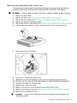
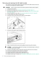
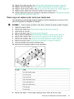
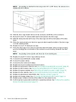
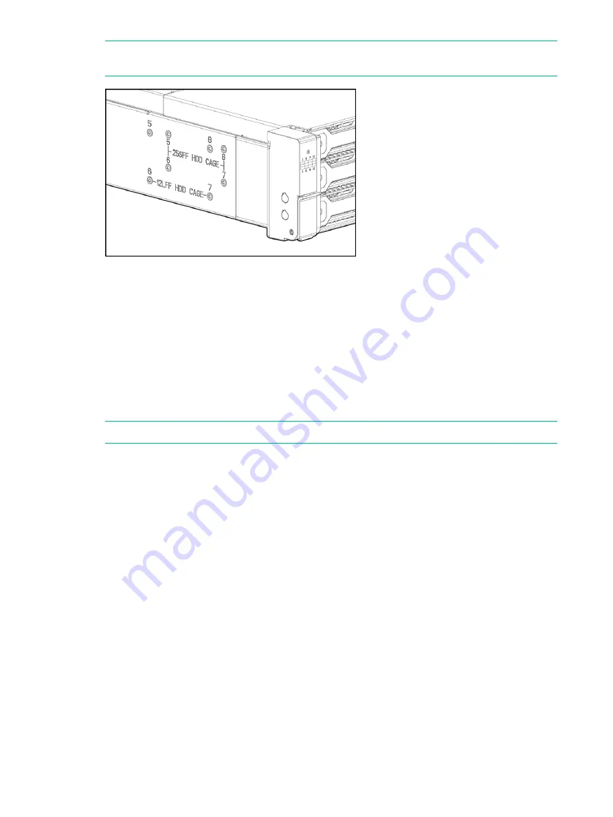
Depending on whether the drive cage is for LFF or SFF drives, the screws are in
slightly different locations.
12.
Slide the drive cage toward the front of the enclosure and lift free of the enclosure.
13.
Remove the two T-15 screws attaching the back plane to the drive cage.
14.
Slide the back plane toward the top of the drive cage and lift the back plane off the drive
cage.
15.
Place the new back plane on the drive cage and slide toward the bottom of the drive cage
on to the retaining hooks.
16.
Replace the two T-15 back plane screws.
17.
Place the drive cage in the enclosure and slide toward the back of the enclosure making
sure the locating pins in the bottom of the enclosure are all correctly located in the drive
cage.
NOTE:
Depending on the specific unit, there are 6 or 8 locating pins.
18.
Replace the eight T-10 drive cage retaining screws.
19.
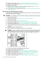
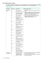
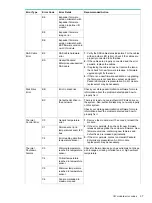
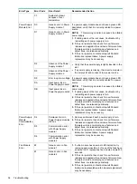
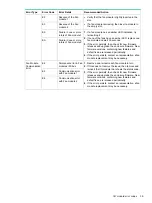
Connect the two UID/Health module cables.
20.
Connect the power cables.
21.
Connect the fan control card cables.
22.
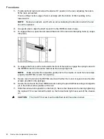
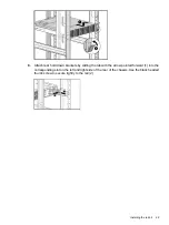
Replace the cover and press lever down to secure.
23.
Replace the enclosure in the rack. See
“Removing and replacing the enclosure” (page 22)
24.
Replace the I/O modules. See
“Removing and replacing the I/O module” (page 18)
25.
Replace the power supplies. See
“Removing and replacing a power supply” (page 18)
26.
Replace the fan modules. See
“Removing and replacing the fan module” (page 19)
27.
Replace the hard drives and/or SSDs. See
28.
Replace I/O module cables. See
“Removing and replacing the I/O module” (page 18)
29.
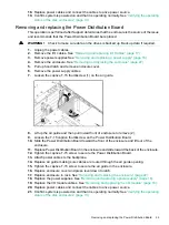
Replace power cables and connect the cables to a live power source.
30.
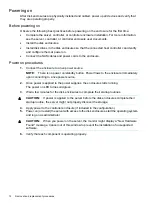
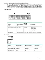
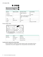
Confirm system is powered on and that it is operating normally. See
status of the disk enclosures” (page 13)
26
Removal and replacement procedures
Содержание D3600
Страница 8: ...8 Removal and replacement procedures ...
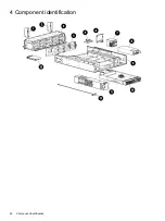
Страница 40: ...4 Component identification 40 Component identification ...

