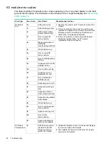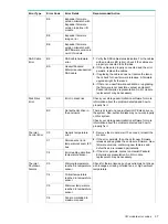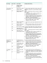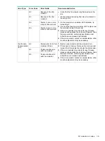
Recognizing disk drive failure
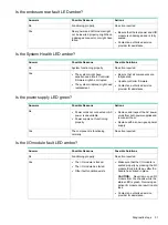
In an Hewlett Packard Enterprise enclosure, a steadily glowing fault LED indicates that a disk
drive has failed. Other indications of failed disk drives are as follows:
•
ACU represents failed drives with a distinctive icon.
•
HPE SIM can detect failed drives remotely across a network. (For more information about
SIM, see the documentation on the Management CD.)
•
ADU lists all failed drives.
•
Operating System log files
For additional information about diagnosing disk drive problems, see the HPE ProLiant servers
troubleshooting guide.
Effects of a disk drive failure
When a disk drive fails, all logical drives that are in the same array are affected. Each logical
drive in an array might be using a different fault-tolerance method, so each logical drive can be
affected differently.
•
RAID0 configurations cannot tolerate drive failure. If any physical drive in the array fails, all
non-fault-tolerant (RAID0) logical drives in the same array also fail.
•
RAID1+0 configurations can tolerate multiple drive failures as long as no failed drives are
mirrored to one another (with no spares assigned).
•
RAID5 configurations can tolerate one drive failure (with no spares assigned).
•
RAID6 with ADG configurations can tolerate simultaneous failure of two drives (with no
spares assigned).
Compromised fault tolerance
If more disk drives fail than the fault-tolerance method allows, fault tolerance is compromised,
and the logical drive fails.
Factors to consider before replacing disk drives
Before replacing a degraded drive:
•
Open SIM and inspect the Error Counter window for each physical drive in the same array
to confirm that no other drives have any errors. For details, see the SIM documentation on
the management cd.
•
Be sure that the array has a current, valid backup.
•
Use replacement drives that have a capacity at least as great as that of the smallest drive
in the array. The controller immediately fails drives that have insufficient capacity.
Recognizing disk drive failure
33
Содержание D3600
Страница 8: ...8 Removal and replacement procedures ...
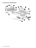
Страница 40: ...4 Component identification 40 Component identification ...

