©Vantage, 9/2/2015 / IS-00709-B
Commercial Power Enclosure Solutions — MODEL: LCAP44A
page 1 of 2
POE SWITCH
COM-POE-SWITCH
EMR. SWITCH
VA-RRU-1-12OV
(277V)
EMR. SWITCH
VA-EPC-DFS-12OV
(277V)
Please see install sheets for
emergency switch applications.
I N S T A L L A T I O N
V A N T A G E C O N T R O L S . C O M
V A N T A G E I N S T A L L G U I D E S
1061 South 800 East, Orem, Utah 84097
●
Telephone: 801 229-2800
●
Fax: 801 224-0355
Commercial Power Enclosure Solutions — MODEL: LCAP44A
Overview
Vantage’s
LCAP Series Commercial Enclosures
ship with pre-
configured modular solutions for commercial, architectural load
dimming and switching. The pre-configured designs save time in
Design Center and installing.
The UL listed LCAP44A panels are adaptable to spaces that have
mixed 0-10V, and PWM loads and HV relay loads via Vantage’s
LVOS-0-10-PWM station. LCAP44A connects to any controller
over the local network for easy connection and scalability.
Solution 1 – Parent-level Enclosure Models
Main Enclosure
Description
LCAP44 44”
Architectural
Enclosure
Optional Parts
Description
VA-RRU-1-120V
Emergency Shunt Relay - 120V
VA-RRU-1-277V
Emergency Shunt Relay - 277V
VA-EPC-DFS-120V Emergency
Lighting Surface Mount Switch 120V
VA-EPC-DFS-277V Emergency
Lighting Surface Mount Switch 277V
Specifications
LCAP44A
Specifications
Cabinet Dimensions
HWD
44.5” x 24” x 4.575” / 113cm x 61cm x 11.6cm
Door Dimensions HWD
44.5” x 24” x 0.75” / 113cm x 61cm x 2cm
Panel Insert HWD
42” x 21” x 4.175” / 106.7cm x 53.3cm x 10.6cm
Weight Enclosure
41 lbs / 18.6 kg
Weight Door
20.7 lbs / 9.39 kg
Weight Panel Insert
23 lbs / 10.43 kg
Number of LVOS-0-10-PWM
*
stations
Up to 6
Analog, 0-10DC/LV — Max. Outputs
Up to 24
PWM, LV — Max. Outputs
Up to 24
HV Relay 120-277 VAC — Max. Outputs
Up to 24
Line Feeds (breakers) required
1 and Up
Enclosure Finish
Galvanized Steel
Door Finish
Black - Powder Coated
Cover
vented, hinged
HV Wire
copper wire, min of 80°C/176°F insulation
Ventilation
maintained 36” front clearance
Ambient Operating Temp.
0-40°C / 32-104°F
Ambient Operating Humidity
5-95% non-condensing
UL, CUL, and CE listed
yes
* See these install sheets for important information:
Low Voltage Output Station Lighting_LVOS-0-10-PWM-1
LCAP Enclosure Designs
LCAP Series Enclosure Facts.
•
Enclosures must be populated from
left to right
and
top down
.
o
Blank positions cannot be left between lighting modules in
Design Center setup.
•
Enclosures are pre-configured and wired (to the extent
possible) using specific combinations of the following
components. Installed components are dependent on the
enclosure design.
o
Components using high voltage wiring.
Mixed high voltage wiring.
o
Components using low voltage control signal wiring.
o
Components using low voltage communication wiring.
o
Components using high voltage and low voltage
connections made inside the enclosure.
•
The enclosure uses built-in barriers to separate high and low
voltage wiring.
o
Some designs include the barrier while other designs
require the barrier be added by the designer.
o
High voltage barriers may be installed between
120V/240V/277V load modules.
•
LCAP44A Enclosures only contain LVOS-0-10-PWM stations.
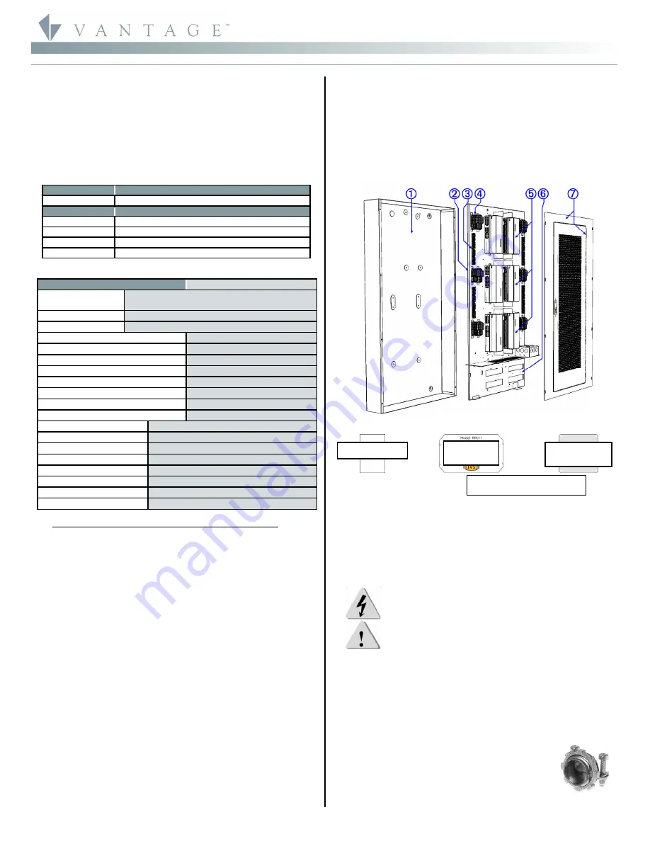
Enclosure Features / Parts
1.
Enclosure can.
2.
Panel Insert
3.
Ground terminals.
4.
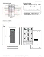
Wiring terminal blocks (see close-up next page).
a.
Internal side pre-wired.
b.
External side wired in field.
5.
Up to 6, LVOS-0-10-PWM stations.
6.
LV section.
7.
Enclosure cover with hinged/vented door allowing easy access
when servicing and proper ventilation for convection cooling
process.
LCAP44A Panel Optional Construction Parts
Installation / Enclosure Mounting Instructions
Installation of Vantage LCAP products should be performed or
supervised by the Vantage factory and/or a
Certified Vantage
Installer.
Installation and maintenance of high voltage devices
should only be performed by
licensed, qualified,
and
competent
personnel having appropriate training and experience.
CAUTION:
Turn Breakers OFF and Check that no Power is ON at
the AC Terminal Boards when working in the
enclosure or working on lighting fixtures connected
to the Module’s Loads, etc. Do not allow trimmed wire
cuttings to fall into enclosure components as they
may cause damage when power is restored. Damage
from this type of short will
void
the warranty.
•
Do not mount enclosures in attics, garages, or crawlspaces,
unless room is properly conditioned to conform to ambient
room temperature and humidity requirements.
•
Mount enclosure a minimum of 18” from ceiling or floor.
•
National Electrical Code requires a minimum frontal clearance
of 36” for the enclosure.
•
Use screws provide for mounting.
General Wiring
Drill proper size holes in can for running wires in
and out of the enclosure. Separate high and low
voltage wire run channels.
All wire runs in and out
of the enclosure should be
secured
using
2-screw
connectors
or equivalent as shown at the right
.
Proper conduit or equivalent wire channels should
be used according to local codes and regulations.


