


23
Configuring the switch at the CLI
The HP 1910 Switch Series can be configured through the CLI, Web interface, and SNMP/MIB. The Web
interface supports all 1910 Switch Series configurations. These configuration methods are suitable for
different application scenarios. The CLI provides configuration commands to facilitate your operation,
which are described in this chapter. To perform configurations not supported by the CLI, use the Web
interface.
You will enter user view directly after you log in to the device. Commands in the document are all
performed in user view.
Getting started with the CLI
The CLI provides configuration commands to facilitate your operation. For example, if you forget the IP
address of VLAN-interface 1 and cannot log in to the device through the Web interface, you can connect
the console port of the device to a PC, and reconfigure the IP address of VLAN-interface 1 at the CLI.
Setting up the configuration environment
CAUTION:
Identify the mark on the console port to make sure you are connecting to the correct port.
To set up the configuration environment, connect a terminal (a PC in this example) to the console port on
the switch with a console cable.
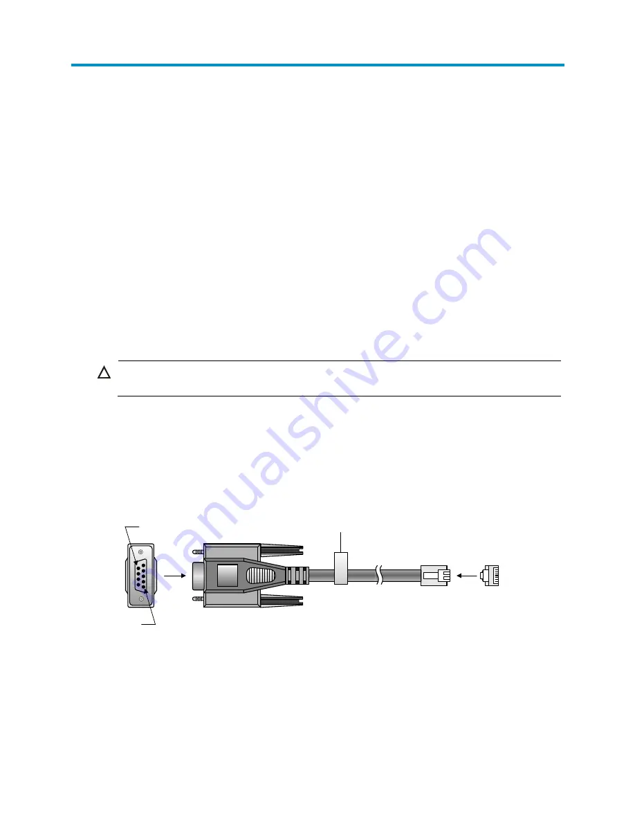
A console cable is an 8-core shielded cable, with a crimped RJ-45 connector at one end for connecting
to the console port of the switch, and a DB-9 female connector at the other end for connecting to the
serial port on the console terminal.
Figure 17
Console cable
Use a console cable to connect a terminal device to the switch, as follows:
1.
Plug the DB-9 female connector to the serial port of the console terminal or PC.
2.
Connect the RJ-45 connector to the console port of the switch.
Main label
1
8
B side
B
Pos.9
Pos.1
A side
A
Содержание Compaq Presario,Presario 1910
Страница 35: ...22 Figure 16 Sort display based on MAC address in the ascending order ...
Страница 54: ...41 Figure 27 Configuration finishes ...
Страница 70: ...57 Figure 42 Configuring idle timeout period 3 Set the idle timeout period for logged in users 4 Click Apply ...
Страница 98: ...85 Figure 67 Displaying the rate settings of ports ...
Страница 114: ...101 Figure 82 Port traffic statistics NOTE When the bandwidth utilization is lower than 1 1 is displayed ...
Страница 158: ...145 Field Description OutErrors Number of invalid packets sent through the interface ...
Страница 202: ...189 Figure 177 Creating a static MAC address entry ...
Страница 230: ...217 Figure 193 Configuring MSTP globally on Switch D ...
Страница 359: ...346 5 View the operation result in the Summary area Figure 316 IPv6 traceroute operation result ...


