Removal and Replacement Procedures
Maintenance and Service Guide
6–41
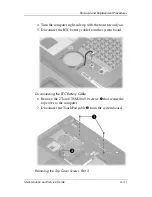
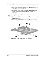
4. Turn the computer right-side up with the front toward you.
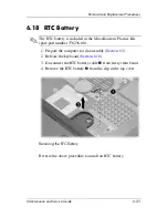
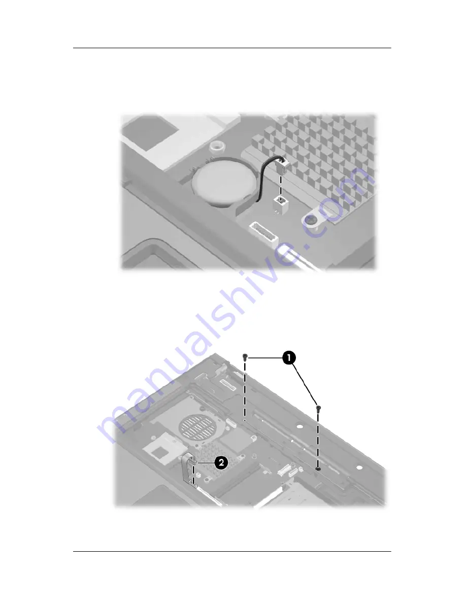
5. Disconnect the RTC battery cable from the system board.
Disconnecting the RTC Battery Cable
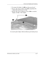
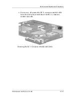
6. Remove the 2 Torx8 T8M2.0×9.0 screws
1
that secure the
top cover to the computer.
7. Disconnect the TouchPad cable
2
from the system board.
Removing the Top Cover Screws, Part 2
Содержание Compaq NC6110
Страница 74: ...4 4 Maintenance and Service Guide Illustrated Parts Catalog Computer Major Components ...
Страница 76: ...4 6 Maintenance and Service Guide Illustrated Parts Catalog Computer Major Components ...
Страница 78: ...4 8 Maintenance and Service Guide Illustrated Parts Catalog Computer Major Components ...
Страница 80: ...4 10 Maintenance and Service Guide Illustrated Parts Catalog Computer Major Components ...
Страница 82: ...4 12 Maintenance and Service Guide Illustrated Parts Catalog Computer Major Components ...
Страница 86: ...4 16 Maintenance and Service Guide Illustrated Parts Catalog 4 5 Mass Storage Devices ...
Страница 229: ...Display Component Recycling Maintenance and Service Guide D 13 23 Remove the LCD panel Removing the LCD Panel ...

