


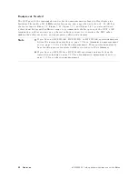


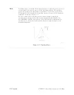


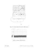
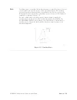


Figure
3-9.
F
aster
Sweep
Times
in
Stimulus-Response
A
uto-Coupled
Mode
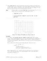
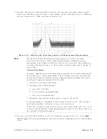
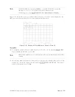
9.
Because
this
test
is
for
bandpass
lter
rejection
only
,
tune
the
spectrum
analyzer
so
the
lter's
roll-o
takes
up
most
of
trace
on
the
display
.
Set
the
start
frequency
to
1
MHz
and
the
stop
frequency
to
1
GHz,
as
shown
in
Figure
3-10 .
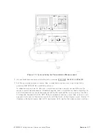
Figure
3-10.
A
djusting
the
Spectrum
Analyzer
for
Measurement
Requirements
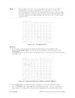
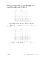
10.
Decrease
resolution
bandwidth
to
reduce
the
displayed
average
noise
level.
Press
4
BW
5
NNNNNNNNNNNNNNNNNNNN
RES
BW
(to
select
MAN),
then
press
4
+
5
on
the
spectrum
analyzer
.
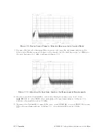
In
Figure
3-11,
resolution
bandwidth
is
set
at
300
kHz.
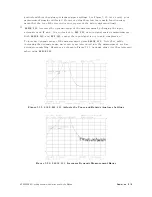
11.
Narrow
video
bandwidth
to
smooth
the
noise;
press
NNNNNNNNNNNNNNNNNNNNNNNNNN
VIDEO
BW
(to
select
MAN),
then
press
4
+
5
on
the
spectrum
analyzer
.
In
Figure
3-11 ,
video
bandwidth
is
set
at
300
Hz.
3-12
Operation
HP
85640A
RF
T
racking
Generator
Operation
and
Service
Manual
Содержание 85640A
Страница 2: ...HP 85640A RF Tracking Generator Operation and Service Manual ABCDE Printed in USA ...
Страница 111: ......
Страница 169: ......


