


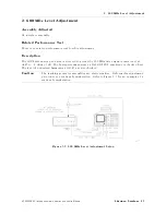


2.
600
MHz
Level
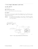
A
djustment
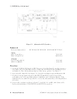
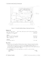
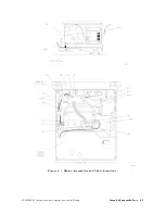
Figure
5-4.
Attenuator
A3U4
Location
Equipment
Host
spectrum
analyzer
.
.
.
.
.
HP
8560A/E,
HP
8561A/B/E,
HP
8562A/B
,
HP
8563A/E
Cables
BNC,
62
cm
(24
in)
.
.
.
.
.
.
.
.
.
.
.
.
.
.
.
.
.
.
.
.
.
.
.
.
.
.
.
.
.
.
.
.
.
.
.
.
.
.
.
.
.
.
.
.
.
.
.
.
.
.
.
.
8120-1839
BNC,
122
cm
(48
in)
.
.
.
.
.
.
.
.
.
.
.
.
.
.
.
.
.
.
.
.
.
.
.
.
.
.
.
.
.
.
.
.
.
.
.
.
.
.
.
.
.
.
.
.
.
.
.
.
.
.
HP
10503A
A
dapters
Type
N
(m)
to
BNC
(f)
.
.
.
.
.
.
.
.
.
.
.
.
.
.
.
.
.
.
.
.
.
.
.
.
.
.
.
.
.
.
.
.
.
.
.
.
.
.
.
.
.
.
.
.
.
.
.
.
.
1250-1476
BNC
(f)
to
SMB
(f)
.
.
.
.
.
.
.
.
.
.
.
.
.
.
.
.
.
.
.
.
.
.
.
.
.
.
.
.
.
.
.
.
.
.
.
.
.
.
.
.
.
.
.
.
.
.
.
.
.
.
.
.
1250-1236
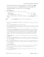
Procedure
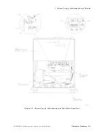
1.
Set
the
HP
85640A
LINE
switch
to
OFF
.
Disconnect
all
cables
from
the
tracking
generator
and
remove
the
cover
assembly
(refer
to
\Removing
and
Replacing
the
Instrument
Cover"
in
Chapter
7).
Place
the
tracking
generator
in
the
service
position.
See
Figure
5-3.
2.
Disconnect
W5
from
A3J5
(see
Figure
5-4).
Turn
the
tracking
generator
LINE
switch
ON.
3.
Check
the
host
spectrum
analyzer's
CAL
OUTPUT
amplitude
using
the
appropriate
performance
test
in
the
spectrum
analyzer's
installation
and
verication
manual.
If
the
amplitude
does
not
meet
the
specication,
correct
the
problem
before
continuing
with
this
procedure
.
4.
Connect
the
equipment
as
shown
in
Figure
5-3
with
the
122
cm
BNC
cable
between
the
host
spectrum
analyzer's
CAL
OUTPUT
and
INPUT
50
connectors
.
5-8
Adjustment
Procedures
HP
85640A
RF
T
racking
Generator
Operation
and
Service
Manual
Содержание 85640A
Страница 2: ...HP 85640A RF Tracking Generator Operation and Service Manual ABCDE Printed in USA ...
Страница 111: ......
Страница 169: ......


