Front-P
anel
F
eatures
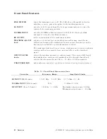
LINE
SWITCH
turns
the
instrument
on
or
o.
The
LED
above
the
switch
indicates
whether
or
not
ac
power
is
applied
to
the
tracking
generator
.
LO
INPUT
uses
the
1st
LO
output
from
the
host
spectrum
analyzer
to
drive
the
tuning
of
the
tracking
generator
.
300
MHz
INPUT
uses
the
300
MHz
calibrator
signal
(3rd
LO)
of
the
host
spectrum
analyzer
to
drive
the
tracking
generator
.
RF
OUTPUT
is
the
output
signal
of
the
tracking
generator
.
TRA
CKING
ADJUST
knob
allows
you
to
adjust
for
any
tracking
errors
that
may
result
from
dierences
between
the
tracking
generator
output
frequency
and
the
frequency
to
which
the
spectrum
analyzer
is
tuned.
The
tracking
adjust
knob
is
non-linear;
clockwise
and
counter-clockwise
rotation
will
not
necessarily
have
an
equal
eect
on
the
displayed
signal.
OUTPUT
LEVEL
knobs
adjust
the
tracking
generator's
output
power
.
The
vernier
(left-hand)
knob
makes
ne-resolution
adjustments
,
while
the
right-hand
knob
adjusts
the
attenuator
from
0
dB
to
070
dB
in
10
dB
increments
.
UNLEVELED
LED
lights
when
an
unleveled
condition
is
detected
(except
during
retrace).
T
able
3-1.
Front-P
anel
Interconnections
Connector
Frequency
Range
Amplitude
Limits
LO
INPUT
(SMA
female)
3.9107
GHz
0
6.8107
GHz
+16.5
dBm
62.0
dB
300
MHz
INPUT
(BNC
female)
N/A
010
dBm
61.0
dB
RF
OUTPUT
(Type
N
female)
300
kHz
0
2.9
GHz
Maximum
output
power:
0
dBm
Minimum
output
power:
080
dBm
3-2
Operation
HP
85640A
RF
T
racking
Generator
Operation
and
Service
Manual
Содержание 85640A
Страница 2: ...HP 85640A RF Tracking Generator Operation and Service Manual ABCDE Printed in USA ...
Страница 111: ......
Страница 169: ......

