buered
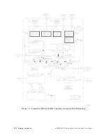
1st
LO
signal
from
the
coupler
.
The
mixer
output
is
then
amplied.
Output
amplier
The
signal
from
the
output
mixer
passes
through
the
low-pass
lter
of
the
output
amplier
,
which
then
amplies
the
signal
to
a
usable
range
.
The
amplier
also
contains
a
detector
for
leveling
the
output.
Bias
board
The
bias
board
houses
the
ALC
circuitry
for
the
tracking
generator
.
It
also
distributes
dc
power
to
the
rest
of
A2.
ALC
inputs
originate
from
the
A3
Interface
Assembly
(for
power
level
control),
from
the
rear-panel
EXT
ALC
INPUT
,
and
from
the
output
amplier
detector
.
The
ALC
loop
drives
the
modulator
.
A3
Interface
Assembly
The
A3
interface
assembly
provides
control
signals
for
the
A2
tracking
generator's
power
level
and
tracking
oscillator
.
A3
also
monitors
A2's
ALC
MON
(ALC
monitor)
line
to
check
for
unleveled
output.
The
A2
tracking
generator
600
MHz
drive
signal
originates
on
A3.
300
MHz
to
600
MHz
converter
This
circuitry
receives
the
host
spectrum
analyzer's
300
MHz,
010
dBm
CAL
OUTPUT
signal.
The
signal
is
doubled
to
600
MHz
to
drive
the
A2
tracking
generator
.
The
converter
consists
of
two
amplication
stages
followed
by
a
frequency
doubler
and
A3U4,
a
factory-selected
attenuator
.
A3U4
is
used
to
set
the
output
power
from
the
converter
to
08
dBm
at
600
MHz.
The
circuit's
300
MHz
notch
lter
eliminates
the
300
MHz
fundamental
signal.
P
ower
level
control
The
power
level
of
the
A2
tracking
generator
is
controlled
by
both
the
front
panel
OUTPUT
LEVEL
vernier
and
the
rear
panel
0.5V/GHz
INPUT
from
the
host
spectrum
analyzer
.
The
0.5V/GHz
INPUT
provides
slope
(atness)
compensation
to
the
output
power
level.
Unlevel
detector
The
A2
tracking
generator
provides
the
ALC
MON
(ALC
monitor)
control
line
to
the
A3
interface
.
The
A2
output
is
leveled
when
ALC
MON
is
between
00.545
V
and
+1.09
V
.
The
unlevel
detector
buers
ALC
MON
and
feeds
this
signal
to
a
window
comparator
.
The
window
comparator
output
is
low
when
the
output
is
unleveled.
It
is
normal
for
the
output
to
be
unleveled
momentarily
during
retrace
.
The
host
spectrum
analyzer's
BLANKING
signal
prevents
a
ashing
UNLEVELED
LED
during
retrace
.
The
BLANKING
signal
is
high
during
retrace
and
low
during
a
sweep
.
P
ower
supply
The
power
supply
circuitry
provides
added
ltering
for
the
+15
V
and
015
V
supplies
and
regulators
for
the
+5
V
and
610
V
supplies
.
Tracking
control
The
tracking
control
circuitry
generates
the
+TUNE
control
line
.
This
control
line
determines
the
A2
tracking
generator's
tracking
oscillator
frequency
.
Tracking
is
controlled
by
setting
the
front
panel
TRA
CKING
ADJUST
potentiometer
and
A3R1
COR
TRA
CK
(coarse
tracking).
Noise
on
the
+TUNE
line
may
cause
residual
FM
on
the
tracking
generator
output.
7-22
Service
Information
HP
85640A
RF
T
racking
Generator
Operation
and
Service
Manual
Содержание 85640A
Страница 2: ...HP 85640A RF Tracking Generator Operation and Service Manual ABCDE Printed in USA ...
Страница 111: ......
Страница 169: ......


