6.
Because
this
test
is
for
bandpass
lter
rejection
only
,
tune
the
spectrum
analyzer
so
the
lter's
roll-o
takes
up
most
of
trace
on
the
display
.
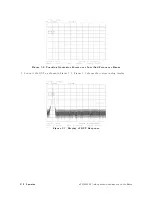
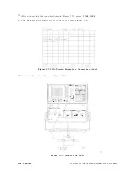
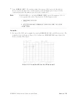
Set
the
start
frequency
to
1
MHz
and
the
stop
frequency
to
1
GHz,
as
shown
in
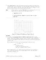
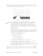
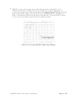
Figure
3-24.
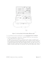
Figure
3-24.
A
djusting
the
Spectrum
Analyzer
for
Measurement
Requirements
Note
HP
8561A
and
HP
8562A/B
spectrum
analyzers
do
not
have
tracking
generator-related
keys
.
Sweep-time
settings
during
a
stimulus-response
measurement
are
highly
dependent
on
the
device
under
test.
Any
changes
to
resolution
bandwidth,
span,
or
other
analyzer
settings
may
cause
a
change
in
sweep
time
.
Setting
Sweeptimes
A
ccurate
stimulus-response
measurements
typically
can
use
sweeptimes
much
faster
than
auto-coupled
sweeptimes
.
The
following
procedure
calculates
the
fastest
sweeptime
for
stimulus-response
measurements
,
assuming
the
span
is
less
than
20
times
the
bandwidth
of
the
DUT:
1.
Note
the
autocoupled
sweeptime
.
2.
Calculate
each
of
the
following:
a.
span
(Hz)
/
156
GHz
b
.
500
/
resolution
bandwidth
(Hz)
c
.
200
/
video
bandwidth
(Hz)
3.
Determine
the
greatest
of
the
values
in
steps
2a,
2b
,
and
2c
.
4.
Set
sweeptime
to
the
smaller
of
the
values
in
steps
1
and
3.
The
analyzer
will
limit
sweeptime
to
50
msec
or
less
in
non-zero
spans
.
If
the
value
in
step
4
is
less
than
the
auto-coupled
sweeptime
,
the
MEAS
UNCAL
indicator
will
be
displayed;
this
message
may
be
ignored,
as
it
has
no
eect
on
the
outcome
of
the
measurement.
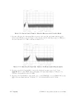
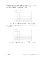
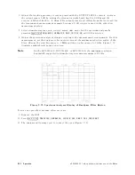
7.
Decrease
resolution
bandwidth
to
reduce
the
displayed
average
noise
level.
Press
4
BW
5
N
NNNNNNNNNNNNNNNNNNN
RES
BW
4
+
5
on
the
spectrum
analyzer
.
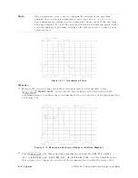
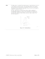
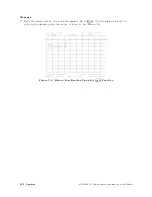
Note
the
decrease
in
amplitude
due
to
the
tracking
error
.
HP
85640A
RF
T
racking
Generator
Operation
and
Service
Manual
Operation
3-23
Содержание 85640A
Страница 2: ...HP 85640A RF Tracking Generator Operation and Service Manual ABCDE Printed in USA ...
Страница 111: ......
Страница 169: ......


