background image

8.

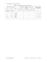
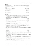
Frequency

Tracking

Range

T

able

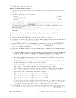
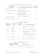
4-9.

P

erformance

T

est

Record

(P

age

2

of

3)

Hewlett-P

ackard

Company

Model

HP

85640A

Report

No

.

Serial

No

.

Date

T

est

No

.

T

est

Description

Results

Measurement

Uncertainty

Min

Measured

Max

1.

Output

attenuator

accuracy

8.

Maximum

cumulative

attenuator

accuracy

010

dB

01.5

dB

+1.5

dB

60.40

dB

020

dB

01.5

dB

+1.5

dB

+0.07/00.08

dB

030

dB

01.5

dB

+1.5

dB

60.09

dB

040

dB

01.5

dB

+1.5

dB

60.10

dB

050

dB

01.5

dB

+1.5

dB

60.11

dB

060

dB

01.5

dB

+1.5

dB

60.12

dB

070

dB

01.5

dB

+1.5

dB

+0.12/00.13

dB

9.

Maximum

step-to-step

attenuator

accuracy

010

dB

00.8

dB

+0.8

dB

60.40

dB

020

dB

00.8

dB

+0.8

dB

60.41

dB

030

dB

00.8

dB

+0.8

dB

+0.11/00.12

dB

040

dB

00.8

dB

+0.8

dB

+0.13/00.14

dB

050

dB

00.8

dB

+0.8

dB

60.15

dB

060

dB

00.8

dB

+0.8

dB

60.16

dB

070

dB

00.8

dB

+0.8

dB

+0.17/00.18

dB

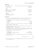
2.

Maximum

leveled

output

power

13.

Maximum

leveled

0

dBm

60.46

dB

output

power

3.

Level

atness

14.

Maximum

atness

+2.0

dB

60.41

dB

15.

Minimum

atness

02.0

dB

60.41

dB

4.

Harmonic

spurious

outputs

12.

2nd

harmonic

level

300

kHz

025

dBc

+1.55/01.80

dB

100

MHz

025

dBc

+1.55/01.80

dB

300

MHz

025

dBc

+1.55/01.80

dB

900

MHz

025

dBc

+1.55/01.80

dB

1.4

GHz

025

dBc

+3.45/04.01

dB

4-36

P

erformance

T

ests

HP

85640A

RF

T

racking

Generator

Operation

and

Service

Manual

Содержание 85640A

Страница 1: ...pany name prefix where a product name number was HP XXXX the current name number is now Agilent XXXX For example model number HP 8648 is now model number Agilent 8648 Contacting Agilent Sales and Service Offices The sales and service contact information in this manual may be out of date The latest service and contact information for your location can be found on the Web at http www agilent com fin...

Страница 2: ...HP 85640A RF Tracking Generator Operation and Service Manual ABCDE Printed in USA ...

Страница 3: ...t be liable for errors contained herein or for incidental or consequential damages in connection with the furnishing performance or use of this material HP part number 85640 90005 Printed July 1992 This manual applies to HP 85640A RF tracking generators with serial numbers pre xed 2918A and below c Copyright Hewlett Packard Company 1989 1992 All Rights Reserved Reproduction adaptation or translati...

Страница 4: ...P from another country HP warrants that its software and rmware designated by HP for use with an instrument will execute its programming instructions when properly installed on that instrument HP does not warrant that the operation of the instrument or software or rmware will be uninterrupted or error free Limitation of Warranty The foregoing warranty shall not apply to defects resulting from impr...

Страница 5: ...iderations Warning Before this instrument is switched on make sure it has been properly grounded through the protective conductor of the ac power cable to a socket outlet provided with protective earth contact Any interruption of the protective grounding conductor inside or outside the instrument or disconnection of the protective earth terminal can result in personal injury Warning There are many...

Страница 6: ...2 2 Installation What You ll Find in This Chapter 2 1 Compatibility with Portable Spectrum Analyzers 2 1 Initial Inspection 2 2 Is the Shipment Complete 2 2 Is the Shipping Container in Good Condition 2 2 Save the Packaging Materials 2 2 Preparing the RF Tracking Generator for Use 2 2 Power Requirements 2 3 Setting the Line Voltage Selector Switch 2 4 Checking the Fuse 2 5 Power Cable 2 5 Connecti...

Страница 7: ...t You ll Find in This Chapter 4 1 What is Performance Veri cation 4 1 Before Beginning 4 3 Test Equipment You ll Need 4 3 Recording Test Results 4 3 1 Output Attenuator Accuracy 4 6 2 Maximum Leveled Output Power 4 9 3 Level Flatness 4 12 4 Harmonic Spurious Outputs 4 16 5 Non Harmonic Spurious Outputs 4 19 6 LO Feedthrough Amplitude 4 25 7 Tracking Generator Feedthrough 4 28 8 Frequency Tracking ...

Страница 8: ... Board Assembly Replacement 7 12 Removal 7 12 Replacement 7 12 A4 Power Supply Replacement 7 14 Removal 7 14 Replacement 7 14 A5 Line Filter Switch Assembly Replacement 7 16 Removal 7 16 Replacement 7 16 HP 85640A RF Tracking Generator Circuit Descriptions and Troubleshooting Procedures 7 18 HP 85640A Block Diagram Circuit Descriptions 7 18 Troubleshooting the HP 85640A RF Tracking Generator Circu...

Страница 9: ...rence Trace in Trace B 3 17 3 17 Normalized Trace 3 18 3 18 Measuring Rejection Range with Delta Markers 3 18 3 19 NNNNNNNNNNNNNNNNNNNNNNNNNNNNNNNNNNNNNN NORM REF LVL Adjusts the Trace and Retains Analyzer Settings 3 19 3 20 NNNNNNNNNNNNNNNNNNNNNNNNNNNNN RANGE LVL Increases Dynamic Measurement Range 3 19 3 21 Tracking Generator Power over Speci ed Frequency Range 3 21 3 22 System Setup for Transmi...

Страница 10: ...p 5 4 5 2 Power Supply Adjustments and Test Point Locations 5 5 5 3 600 MHz Level Adjustment Setup 5 7 5 4 Attenuator A3U4 Location 5 8 5 5 Power Level Adjustment Setup 5 12 5 6 Power Level Adjustment and Test Point Locations 5 13 5 7 Tracking Oscillator Range Adjustment 5 15 5 8 Tracking Oscillator Range Adjustment Locations 5 16 6 1 Major Assemblies and Cable Locations 6 3 6 2 Mechanical Replace...

Страница 11: ...ponse Amplitudes 4 23 4 7 Non Harmonic Spurious Responses 4 24 4 8 Tracking Generator Feedthrough 4 31 4 9 Performance Test Record Page 1 of 3 4 35 4 9 Performance Test Record Page 2 of 3 4 36 4 9 Performance Test Record Page 3 of 3 4 37 5 1 Adjustment Procedures and Equipment Used 5 2 5 2 Post Repair or Speci cation Failure Adjustment List 5 3 5 3 Adjustable Components 5 3 5 4 Factory Selectable ...

Страница 12: ...es steps to adjust assemblies of the tracking generator Chapter 6 Assembly Replaceable Parts shows the replaceable parts of the tracking generator Chapter 7 Service Information describes replacement procedures suggests methods for troubleshooting and explains how to return the instrument for service or repair In this chapter you ll also nd lists of component level replaceable parts instrument bloc...

Страница 13: ...uency is controlled by the spectrum analyzer The front panel tracking control enables the tracking generator s output frequency to be matched exactly to the spectrum analyzer input frequency minimizing tracking errors Tracking errors appear as a decrease in the displayed signal amplitude when the resolution bandwidth of the spectrum analyzer signal is decreased The HP 85640A can be leveled externa...

Страница 14: ... 8120 1839 1 cable with SMA m connectors 5061 9038 2 fuses 1A 250V UL CSA for 100 120V operation 2110 0823 or 2 fuses 0 5A 250V IEC for 220 240V operation 210 0824 Figure 1 1 HP 85640A with Accessories Supplied HP 85640A RF Tracking Generator Operation and Service Manual General Information 1 3 ...

Страница 15: ...tor The serial number has two parts a pre x the rst four numbers and a letter and a su x the last ve numbers See Figure 1 2 The rst four numbers of the pre x are a code identifying the date of the last major design change incorporated in your analyzer The letter identi es the country in which the unit was manufactured The ve digit su x is a sequential number and is di erent for each unit Whenever ...

Страница 16: ... calibration cycle all environmental requirements met tracking generator used with one of the compatible spectrum analyzers listed in Table 1 1 HP 85640 Speci cations Characteristics provide useful but non warranted information in the form of typical nominal or approximate values for tracking generator performance See Table 1 2 for a list of tracking generator characteristics HP 85640A RF Tracking...

Страница 17: ...cy Speci cations Frequency Range 300 kHz to 2 9 GHz Minimum Resolution Bandwidth Supported HP 8561A HP 8562A B 100 Hz HP 8560A E HP 8561B E HP 8563A E 300 Hz 1 6 General Information HP 85640A RF Tracking Generator Operation and Service Manual ...

Страница 18: ...o 0 dBm and attenuator set to 010 dB 010 dBm output power Harmonic spurious 300 kHz to 2 9 GHz 025 dBc Non harmonic spurious 300 kHz to 2 0 GHz 027 dBc 2 0 GHz to 2 9 GHz 023 dBc LO feedthrough 3 9 GHz to 6 8 GHz 026 dBm Dynamic Range Tracking generator feedthrough Spectrum analyzer set to 300 Hz resolution bandwidth and 0 dB input attenuation 300 kHz to 1 MHz 095 dBm 1 MHz to 2 0 GHz 0115 dBm 2 0...

Страница 19: ...ly CE03 narrowband Full limits CE03 broadband 20 dB relaxation from 15 kHz to 100 kHz Conducted susceptibility CS01 Full limits CS02 Full limits CS06 Full limits Radiated emissions RE01 15 dB relaxation of 30 kHz exceptioned from 30 kHz to 50 kHz RE02 Full limits to 1 GHz Radiated susceptibility RS03 Limited to 1 V m from 14 kHz to 1 GHz with 20 dB relaxation IF frequencies 30 dB relaxation at spe...

Страница 20: ...umidity 95 at 40 C for 5 days Altitude Operating 15 000 ft Non operating 50 000 ft Vibration 5 to 15 Hz 0 060 in peak to peak excursion 15 to 25 Hz 0 040 in peak to peak excursion 25 to 55 Hz 0 020 in peak to peak excursion Pulse Shock Half Sine 30 g for 11 ms duration Transit Drop 8 in drop on 6 faces and 8 corners HP 85640A RF Tracking Generator Operation and Service Manual General Information 1...

Страница 21: ...s with HP 8560A E HP 8561A B E HP 8562A B and HP 8563A E portable spectrum analyzers Weight 8 4 kg 18 5 lb Dimensions A 337 6 mm 13 5 in wide B 461 1 mm 18 3 in long C 138 6 mm 5 5 in deep Except HP 8560A E Option 002 This option does not provide su cient 1st LO drive to the HP 85640A 1 10 General Information HP 85640A RF Tracking Generator Operation and Service Manual ...

Страница 22: ...n a 1 kHz RES BW after 5 min Usable in a 300 Hz RES BW after 30 min Amplitude Characteristics Output Range 2 8 dBm to 080 dBm Output Attenuator Repeatability 60 2 dB E ective Source Match 0 dB attenuator setting 1 92 1 10 dB attenuator setting 1 33 1 Dynamic Range 300 Hz RES BW 0 dB input attenuation 300 kHz to 1 MHz 95 dB 1 MHz to 2 0 GHz 115 dB 2 0 GHz to 2 9 GHz 110 dB HP 85640A RF Tracking Gen...

Страница 23: ...0 5 V GHz of tuned frequency BLANKING INPUT Connector BNC female rear panel Input amplitude During sweep Low TTL level During retrace High TTL level EXT ALC INPUT Connector BNC female rear panel Impedance 10 k Polarity Negative RF OUTPUT Connector Type N female front panel Impedance 50 Maximum safe reverse level 30 dBm 30 V dc Output VSWR See Table 1 1 HP 85640A Characteristics Amplitude Character...

Страница 24: ... ce addresses Compatibility with Portable Spectrum Analyzers The HP 85640A is compatible with these portable spectrum analyzers Table 2 1 Host Spectrum Analyzer to Tracking Generator Compatibility Spectrum Analyzer Model Numbers Serial Number HP 8560A all serials of non Option 002 HP 8560E all serials of non Option 002 HP 8561A all serials HP 8561B all serials HP 8561E all serials HP 8562A all ser...

Страница 25: ... you ship your instrument or return it for service or repair If the original materials are not available you may order replacements from any HP sales and service o ce see Table 2 3 Instructions for repackaging the HP 85640A are in Returning the RF Tracking Generator for Service in Chapter 7 Preparing the RF Tracking Generator for Use The RF tracking generator must be properly connected to one of t...

Страница 26: ... 100 120 V ac Operation 220 240 V ac Operation Line Voltage 100 V to 120 V 610 220 V to 240 V 610 Line Current 1 A rms max 0 5 A rms max Line Frequency 47 Hz to 66 Hz 47 Hz to 66 Hz HP 85640A RF Tracking Generator Operation and Service Manual Installation 2 3 ...

Страница 27: ...0 or 240 V corresponding to the available ac voltage Insert a small screwdriver or similar tool in the line module door slot and gently pry open the door Rotate the voltage barrel to the appropriate value Figure 2 1 Voltage Selection Switch and Line Fuse Locations 2 4 Installation HP 85640A RF Tracking Generator Operation and Service Manual ...

Страница 28: ...n personal injury Before turning on the tracking generator you must connect its protective earth terminals to the protective conductor of the main power cable Insert the main power cable plug only into a socket outlet that has a protective earth contact Do not defeat the earth grounding protection by using an extension cable power cable or auto transformer without a protective ground conductor If ...

Страница 29: ...Figure 2 2 AC Power Cables Available 2 6 Installation HP 85640A RF Tracking Generator Operation and Service Manual ...

Страница 30: ... cable connections between the tracking generator and an HP 8561B spectrum analyzer Any of the compatible spectrum analyzers is connected to the same inputs and outputs as illustrated in these gures Note Connect the cables with the tracking generator placed beneath the portable spectrum analyzer to prevent the cables from obscuring your view of the display during operation Figure 2 3 Front Panel C...

Страница 31: ...he tracking generator does not seem to function properly the rst time you turn it on turn the power o and refer to the cable connection illustrations in Figure 2 3 and Figure 2 4 If the cable connections appear to be correct contact one of the HP sales and service o ces listed in Table 2 3 2 8 Installation HP 85640A RF Tracking Generator Operation and Service Manual ...

Страница 32: ...o obtain servicing information or to order replacement parts contact the nearest Hewlett Packard sales and service o ce listed in Table 2 3 In any correspondence be sure to include the pertinent information about model numbers serial numbers or assembly part numbers HP 85640A RF Tracking Generator Operation and Service Manual Installation 2 9 ...

Страница 33: ...Meyrin 2 Geneva Zone D Activite De Courtaboeuf 6000 Frankfurt 56 Switzerland F 91947 Les Ulis Cedex West Germany 41 22 780 8111 France 49 69 500006 0 33 1 69 82 60 60 Great Britain Hewlett Packard Ltd Eskdale Road Winnersh Triangle Wokingham Berkshire RF11 5DZ England 44 734 696622 INTERCON FIELD OPERATIONS Headquarters Australia Canada Hewlett Packard Company Hewlett Packard Australia Ltd Hewlett...

Страница 34: ...ng generator you ll learn about Using front and rear panel features Connecting the tracking generator to an HP host portable spectrum analyzer Making a simple transmission measurement Making a simple re ection measurement HP 85640A RF Tracking Generator Operation and Service Manual Operation 3 1 ...

Страница 35: ...ctrum analyzer is tuned The tracking adjust knob is non linear clockwise and counter clockwise rotation will not necessarily have an equal e ect on the displayed signal OUTPUT LEVEL knobs adjust the tracking generator s output power The vernier left hand knob makes ne resolution adjustments while the right hand knob adjusts the attenuator from 0 dB to 070 dB in 10 dB increments UNLEVELED LED light...

Страница 36: ...Figure 3 1 Front Panel Feature Overview HP 85640A RF Tracking Generator Operation and Service Manual Operation 3 3 ...

Страница 37: ...uses the spectrum analyzer s blanking output to deactivate the unleveled LED during retrace 0 5V GHZ INPUT uses the 0 5 V GHz output from the spectrum analyzer for atness compensation Table 3 2 Rear Panel Interconnections Connector Amplitude Voltage Limits EXT ALC INPUT BNC female 0 to 01 V operating 615 V damage level BLANKING INPUT BNC female TTL high during retrace TTL low during sweep 0 5 V GH...

Страница 38: ...ectrum Analyzer Connections Tracking Generator to Spectrum Analyzer Front panel connections 1ST LO INPUT to 1ST LO OUTPUT 300 MHz INPUT to CAL OUTPUT Rear panel connections 0 5 V GHz INPUT to LO SWPj0 5V GHz OUTPUT BLANKING INPUT to BLANKING OUTPUT or BLKG GATE OUTPUT Figure 3 3 Tracking Generator to Host Analyzer Front Panel Connections HP 85640A RF Tracking Generator Operation and Service Manual...

Страница 39: ...r HP 8563A E press 4AUX CTRL5 NNNNNNNNNNNNNNNNNNNNNNNNNNNNNNNN REAR PANEL NNNNNNNNNNNNNNNNNNNNNNNNNNNNNNNNNNNNNNNNN 5V GHZ FAV To view the tracking generator s output connect the tracking generator s RF OUTPUT directly to the host spectrum analyzer s INPUT 50 connector The spectrum analyzer should be tuned between 300 kHz and 2 9 GHz within the speci ed range of the tracking generator On an HP 856...

Страница 40: ... is a typical re ection measurement Because it is a narrowband system the tracking generator s output frequency tracks the spectrum analyzer s input frequency resulting in a wide dynamic range This wide dynamic range is illustrated in the following simpli ed block diagram Figure 3 5 Host Spectrum Analyzer and Tracking Generator System Block Diagram Making a Stimulus Response Measurement There are ...

Страница 41: ...r to replace the DUT when making the reference trace and appropriate cables and adapters Note If you have an HP 8560A E HP 8561B E or HP 8563A E spectrum analyzer follow the instructions starting on page 3 9 for a transmission measurement and on page 3 30 for a re ection measurement These spectrum analyzers have tracking generator related softkeys included in their rmware If you have an HP 8561A o...

Страница 42: ...z5 NNNNNNNNNNNNNNNNNNNNNNNNNNNNN STOP FREQ 2 9 4GHz5 4 Select the 0 5 V GHz OUTPUT on the spectrum analyzer by pressing 4AUX CONTROL5 NNNNNNNNNNNNNNNNNNNNNNNNNNNNNNNN REAR PANEL NNNNNNNNNNNNNNNNNNNNNNNNNNNNNNNNNNNNNN 5V GHZ FAV On an HP 8560E HP 8561E or HP 8563E press 4SWEEP5 NNNNNNNNNNNNNNNNNNNNNNNNNN GATE OFF 5 Adjust the tracking generator s output power with the OUTPUT LEVEL controls set the ...

Страница 43: ... Power over Speci ed Frequency Range 6 Connect the DUT as shown in Figure 3 8 Figure 3 7 shows the corresponding display Figure 3 7 Display of DUT Response 3 10 Operation HP 85640A RF Tracking Generator Operation and Service Manual ...

Страница 44: ... mode the auto coupled sweep times usually are much faster for swept response measurements Stimulus response auto coupled sweep times typically are valid in stimulus response measurements where the system s frequency span is less than 20 times the bandwidth of the DUT When a stimulus response sweep time is chosen an E appears in the special functions area at the left hand side of the display scree...

Страница 45: ...trum Analyzer for Measurement Requirements 10 Decrease resolution bandwidth to reduce the displayed average noise level Press 4BW5 NNNNNNNNNNNNNNNNNNNN RES BW to select MAN then press 4 5 on the spectrum analyzer In Figure 3 11 resolution bandwidth is set at 300 kHz 11 Narrow video bandwidth to smooth the noise press NNNNNNNNNNNNNNNNNNNNNNNNNN VIDEO BW to select MAN then press 4 5 on the spectrum ...

Страница 46: ...in amplitude due to the tracking error Compensate for any tracking errors with the TRACKING ADJUST vernier knob on the HP 85640A see Figure 3 12 Figure 3 12 Using Tracking Adjust to Compensate for Tracking Error HP 85640A RF Tracking Generator Operation and Service Manual Operation 3 13 ...

Страница 47: ...causes a decrease of the displayed amplitude as shown in Figure 3 13 Because a small error in tracking causes a larger change in amplitude tracking errors are most noticeable in narrow resolution bandwidths Use the TRACKING ADJUST vernier knob on the HP 85640A to compensate for tracking errors Adjust the knob until the displayed signal increases to its maximum amplitude Figure 3 13 Tracking Error ...

Страница 48: ...the DUT removed from the system For re ection measurements an open short average is used Because you are making a transmission measurement a thru reference trace must be stored To store the thru trace 13 Press 4AUX CTRL5 NNNNNNNNNNNNNNNNNNNNNNNNNNNNNNNNNNNNNNNNNNNNNNNNNNNNN TRACKING GENRATOR NNNNNNNNNNNNNNNNNNNNNNNNNNNNNNNNNNNNNNNNNNNNNNN SOURCE CAL MENU NNNNNNNNNNNNNNNNNNNNNNNNNN CAL THRU 14 The ...

Страница 49: ...Figure 3 15 Thru Connected for Guided Calibration Routines 3 16 Operation HP 85640A RF Tracking Generator Operation and Service Manual ...

Страница 50: ...NNNNNNNNN STORE THRU Figure 3 16 Display of Thru Reference Trace in Trace B Normalize 16 To normalize press 4AUX CTRL5 NNNNNNNNNNNNNNNNNNNNNNNNNNNNNNNNNNNNNNNNNNNNNNNNNNNNNNNN TRACKING GENERATOR NNNNNNNNNNNNNNNNNNNNNNNNNNNNNNNNNNNNNNNNNNNNNNN NORMLIZE ON OFF until ON is selected Notice that an arrow appears on each side of the graticule when normalization is activated These arrows mark the normali...

Страница 51: ...NNNNNNNNNNNNNNNNNNNNNNNNNNNNNNN MARKER DELTA and adjust the vernier knob on the front panel of the spectrum analyzer to position the second marker in the rejection area of the bandpass lter See Figure 3 18 Figure 3 18 Measuring Rejection Range with Delta Markers 18 Press 4AMPLITUDE5 note that activating normalization changes the NNNNNNNNNNNNNNNNNNNNNNN REF LVL softkey label to NNNNNNNNNNNNNNNNNNNN...

Страница 52: ...N RANGE LVL and NNNNNNNNNNNNNNNNNNNNNNN REF LVL ensure the input signal is not in gain compression To increase dynamic range of the measurement press NNNNNNNNNNNNNNNNNNNNNNNNNNNNN RANGE LVL Note that while increasing the dynamic range more errors are introduced into the measurement such as attenuator switching However as shown in Figure 3 20 dynamic range level has increased when using NNNNNNNNNNN...

Страница 53: ...hand corner of the display In the case shown in Figure 3 20 the passband information has been adjusted o screen in order to view the rejection range with better resolution Changing the analyzer settings to raise the pass band information above the top of the screen causes an ERR 903 A DLMT 3 20 Operation HP 85640A RF Tracking Generator Operation and Service Manual ...

Страница 54: ...er by pressing 4SWEEP5 NNNNNNNNNNNNNNNNNNNNNNNNNNNNNNNNNNNNNNNNNNNNNNN REAR PNL OUTPUT NNNNNNNNNNNNNNNNNNNNNNNNNNNNNNNNNNNNNN 5V GHZ FAV On an HP 8560E HP 8561E or HP 8563E press 4SWEEP5 NNNNNNNNNNNNNNNNNNNNNNNNNN GATE OFF 4 Adjust the tracking generator s output power with the OUTPUT LEVEL controls set the output power of the tracking generator to 010 dBm by setting the attenuator right hand knob...

Страница 55: ...Figure 3 22 System Setup for Transmission Measurement Figure 3 23 Display of DUT Response 3 22 Operation HP 85640A RF Tracking Generator Operation and Service Manual ...

Страница 56: ...ng procedure calculates the fastest sweeptime for stimulus response measurements assuming the span is less than 20 times the bandwidth of the DUT 1 Note the autocoupled sweeptime 2 Calculate each of the following a span Hz 156 GHz b 500 resolution bandwidth Hz c 200 video bandwidth Hz 3 Determine the greatest of the values in steps 2a 2b and 2c 4 Set sweeptime to the smaller of the values in steps...

Страница 57: ...300 Hz 9 Recalculate the sweeptime as described in the note above Figure 3 25 Decrease Resolution Bandwidth to Improve Sensitivity 10 Use TRACKING ADJUST on the HP 85640A to compensate for any tracking errors see Figure 3 26 Figure 3 26 Using TRACKING ADJUST to Compensate for Tracking Error 3 24 Operation HP 85640A RF Tracking Generator Operation and Service Manual ...

Страница 58: ...causes a decrease of the displayed amplitude as shown in Figure 3 27 Because a small error in tracking causes a larger change in amplitude tracking errors are most noticeable in narrow resolution bandwidths Use the TRACKING ADJUST vernier knob on the HP 85640A to compensate for tracking errors Adjust the knob until the displayed signal increases to its maximum amplitude Figure 3 27 Tracking Error ...

Страница 59: ...open short average is used Because you are making a transmission measurement a thru reference trace must be stored To store the thru trace 11 Remove the DUT replacing it with a barrel connector for optimum measurement integrity Connect the thru as shown in Figure 3 28 Figure 3 28 Thru Connected for Calibration Routine 12 Store the thru trace in trace B by pressing 4TRACE5 NNNNNNNNNNNNNNNNNNNNNNN T...

Страница 60: ...e Figure 3 29 Display of Thru Reference Trace in Trace B Normalize 14 To normalize activate the trace math function A0B DL A by pressing 4TRACE5 NNNNNNNNNNNNNN MORE Press NNNNNNNNNNNNNNNNNNNNNNNNNNNNNNNNNNNNNNNNNNNNNNNNNN A0B DL A ON OFF to select ON Note When trace math is on an M will appear in the special functions section of the display 15 If necessary make adjustments to the position of the t...

Страница 61: ...ers Press 4PEAK SEARCH5 NNNNNNNNNNNNNNNNNNNNNNNNNNNNNNNNNNNNNN MARKER DELTA and adjust the vernier knob on the front panel of the spectrum analyzer to position the second marker in the rejection area of the bandpass lter See Figure 3 31 Figure 3 31 Measuring Rejection Range with Delta Markers 3 28 Operation HP 85640A RF Tracking Generator Operation and Service Manual ...

Страница 62: ...ement press 4AMPLITUDE5 NNNNNNNNNNNNNNNNNNNNNNN REF LVL 4 5 Note that while increasing the dynamic range more errors are introduced into the measurement Figure 3 32 shows the results of increasing the dynamic range Notice that the top of the screen does not necessarily represent the gain compression limit Figure 3 32 Increased Dynamic Measurement Range HP 85640A RF Tracking Generator Operation and...

Страница 63: ...e 3 3 2 Select the 0 5 V GHz OUTPUT on the spectrum analyzer by pressing 4SWEEP5 NNNNNNNNNNNNNNNNNNNNNNNNNNNNNNNNNNNNNNNNNNNNNNN REAR PNL OUTPUT NNNNNNNNNNNNNNNNNNNNNNNNNNNNNNNNNNNNNN 5V GHZ FAV On an HP 8560E HP 8561E or HP 8563E press 4SWEEP5 NNNNNNNNNNNNNNNNNNNNNNNNNN GATE OFF 3 Examine the tracking generator s output power by connecting its RF OUTPUT directly to the spectrum analyzer s INPUT 5...

Страница 64: ...Figure 3 33 System Setup for a Re ection Measurement Figure 3 34 Display with System Con gured for a Re ection Measurement HP 85640A RF Tracking Generator Operation and Service Manual Operation 3 31 ...

Страница 65: ...to the measurement requirements For this measurement set the analyzer to frequencies around the minimum re ection region of the lter Change the start frequency to 1 MHz and the stop frequency to 1 GHz Figure 3 35 illustrates what should appear on screen Note On the HP 8560A E HP 8561B E or HP 8563A E the minimum resolution bandwidth supported in stimulus response measurements is 300 Hz Figure 3 35...

Страница 66: ...Figure 3 36 On Screen Prompts to Connect an Open Figure 3 37 Connect the Open HP 85640A RF Tracking Generator Operation and Service Manual Operation 3 33 ...

Страница 67: ...NNNNNNNN STORE OPEN 13 The analyzer will prompt you to connect the short Figure 3 38 Figure 3 38 On Screen Prompts to Connect an Short 14 Connect the short as shown in Figure 3 39 Figure 3 39 Connect the Short 3 34 Operation HP 85640A RF Tracking Generator Operation and Service Manual ...

Страница 68: ...NNNNNNNNNNN SAVE LOCK OFF b 4AUX CTRL5 NNNNNNNNNNNNNNNNNNNNNNNNNNNNNNNNNNNNNNNNNNNNNNNNNNNNNNNN TRACKING GENERATOR NNNNNNNNNNNNNNNNNNNNNNNNNNNNNNNNNNNNNNNNNNNNNNN SOURCE CAL MENU NNNNNNNNNNNNNNNNNNNNNNNNNNNNN CAL SHORT NNNNNNNNNNNNNNNNNNNNNNNNNNNNNNNNNNN STORE SHORT Normalize 16 Reconnect the DUT and normalize by pressing NNNNNNNNNNNNNNNNNNNNNNNNNNNNNNNNNNNNNNNNNNNNNNN NORMLIZE ON OFF until ON is ...

Страница 69: ...the marker Press 4MKR5 Use the analyzer s knob to position the marker at the frequency of interest See Figure 3 41 Figure 3 41 Return Loss Reading Using the 4MKR5 Function 3 36 Operation HP 85640A RF Tracking Generator Operation and Service Manual ...

Страница 70: ...ote HP 8561A and HP 8562A B spectrum analyzers do not have tracking generator related keys Sweep time settings during a stimulus response measurement are highly dependent on the device under test Any changes to resolution bandwidth span or other analyzer settings may cause a change in sweep time Setting Sweeptimes Accurate stimulus response measurements typically can use sweeptimes much faster tha...

Страница 71: ...e corresponding display is illustrated in Figure 3 42 Figure 3 42 Display with the System Con gured for a Re ection Measurement Figure 3 43 System Setup for a Re ection Measurement 3 38 Operation HP 85640A RF Tracking Generator Operation and Service Manual ...

Страница 72: ...owever this measurement can be done via remote operation The program should perform the following steps 1 Read the open trace 2 Read the short trace 3 Average the two traces 4 Put the average trace into trace B For more information refer to the host analyzer s operating and programming manual and to the HP 85620A Mass Memory Module Operating and Programming Manual 7 On HP 8561A and HP 8562A B host...

Страница 73: ...DL A ON OFF until ON is selected 13 If necessary make adjustments to the position of the trace by changing the position of the display line Access the display line by pressing 4DISPLAY5 NNNNNNNNNNNNNNNNNNNNNNNNNNNNNNNNNNNNNNNNNNNNNNN DSPL LIN ON OFF The preset value of the display line is 0 dBm Measure 14 Read the return loss by activating the marker Press PEAK SEARCH 4ON5 NNNNNNNNNNNNNNNNNNNNNNNN...

Страница 74: ... following may serve as the host spectrum analyzer HP 8560A E spectrum analyzer non Option 002 HP 8561A B E spectrum analyzer HP 8562A B spectrum analyzer HP 8563A E spectrum analyzer What is Performance Veri cation The highest level testing called performance veri cation tests the tracking generator s performance against all its speci cations listed in Table 1 1 Table 4 1 lists all performance ve...

Страница 75: ...ve spectrum analyzer Host spectrum analyzer 6 LO feedthrough amplitude Microwave spectrum analyzer Host spectrum analyzer 7 Tracking generator feedthrough 50 termination Host spectrum analyzer 8 Frequency tracking range Frequency counter Power splitter Host spectrum analyzer A host spectrum analyzer can be any one of these models HP 8560A or HP 8560E spectrum analyzer non Option 002 HP 8561A HP 85...

Страница 76: ...nded test equipment for the tracking generator s adjustment procedures located in Chapter 5 Adjustment Procedures and the troubleshooting procedures in Chapter 7 Service Information Note Each host spectrum analyzer has a required warm up time refer to Table 1 1 in the appropriate installation and veri cation manual for speci cations Each performance test in this section describes setting your host...

Страница 77: ...y Option 001 External frequency reference input Measuring receiver Compatible with power sensor HP8902A P A T dB relative mode Resolution 0 01 dB Reference accuracy 61 2 Tuned RF level mode Tuned RF level accuracy 60 15 dB Tuned RF level frequency range 300 MHz 61 MHz Power sensor Frequency range 300 kHz to 2 9 GHz HP 8482A P A T Maximum SWR 1 1 1 MHz to 2 0 GHz 1 30 2 0 GHz to 2 9 GHz Digital Vol...

Страница 78: ...cm 24 in Cable 50 Coaxial Connectors BNC m HP 10502A P A two required Length 23 cm 9 in Cable 50 Coaxial Connectors BNC m HP 10503A P A two required Length 122 cm 48 in Cable Frequency range dc to 300 MHz HP 8120 1839 P A three required Connectors BNC m both ends Length 62 cm 24 in Cable Frequency range 3 9 to 6 9 GHz HP 5061 9038 P A T Maximum SWR 1 4 1 Maximum insertion loss 1 5 dB Connectors SM...

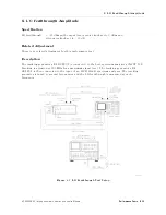
Страница 79: ...analyzer s INPUT 50 Tracking is adjusted at 300 MHz for a maximum signal level The tracking generator s RF OUTPUT is then connected to the input of a measuring receiver The measuring receiver used in its tuned RF level TRFL mode measures the tracking generator s output attenuator accuracy relative to the 0 dB attenuator setting The step to step error is calculated Figure 4 2 Output Attenuator Accu...

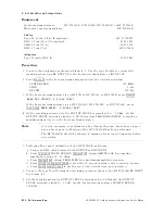
Страница 80: ... on the host spectrum analyzer 5 Set the tracking generator OUTPUT LEVEL vernier to 0 dBm Do not readjust the OUTPUT LEVEL vernier control for the remainder of this test 6 Connect the type N cable to the tracking generator RF OUTPUT and the measuring receiver INPUT 50 connectors 7 On the measuring receiver press the blue shift key AUTOMATIC OPERATION INSTR PRESET FREQ 4MHz5 INPUT FREQ gold shift k...

Страница 81: ...ttenuator Setting Attenuator Accuracy Measurement Uncertainty dB Cumulative dB Step to Step dB dB 0 0 Ref 0 Ref 0 Ref 010 60 40 020 0 07 00 08 030 60 09 040 60 10 050 60 11 060 60 12 070 0 12 00 13 4 8 Performance T ests HP 85640A RF Tracking Generator Operation and Service Manual ...

Страница 82: ...e UNLEVELED indicator is monitored to check for an unleveled condition If the UNLEVELED indicator is not activated during the sweep the tracking generator meets this speci cation If the UNLEVELED indicator is activated during the sweep the OUTPUT LEVEL vernier setting is decreased until the output remains leveled during the entire sweep This setting is recorded Figure 4 3 Maximum Leveled Output Po...

Страница 83: ...erly aligning the pointer with the scale marking 5 Set the tracking generator OUTPUT LEVEL vernier precisely to 0 dBm Locate the groove on the vernier knob closest to the pointer on the knob Follow this groove down the knob to the front panel Align this groove with the front panel 0 mark 6 Disconnect the type N cable from the tracking generator RF OUTPUT Terminate the RF OUTPUT using the 50 termin...

Страница 84: ...ing is achieved that results in a leveled output during the entire sweep 13 Record the power level value indicated by the OUTPUT LEVEL vernier as the maximum leveled output power Maximum leveled output power dBm HP 85640A RF Tracking Generator Operation and Service Manual Performance T ests 4 11 ...

Страница 85: ...F OUTPUT is then connected to a calibrated power sensor and the power level is measured at 300 MHz The measuring receiver is set to RATIO mode so that subsequent power level readings are dB relative to the power level at 300 MHz The tracking generator is stepped through several frequencies within its range The output power di erence relative to the power level at 300 MHz is measured at each freque...

Страница 86: ...the tracking generator set the OUTPUT LEVEL vernier knob to 05 dBm Set the OUTPUT LEVEL attenuator knob to 0 dB then adjust TRACKING ADJUST to display a maximum signal amplitude on the host spectrum analyzer 5 Zero and calibrate the measuring receiver power sensor combination in log mode power level readings are in dBm Enter the power sensor s 300 MHz calibration factor into the measuring receiver...

Страница 87: ...n be used to tune to center frequencies above 100 MHz 14 Record the most positive atness reading in Table 4 4 as the maximum atness Maximum atness dB 15 Record the most negative atness reading in Table 4 4 as the Minimum Flatness Minimum atness dB 4 14 Performance T ests HP 85640A RF Tracking Generator Operation and Service Manual ...

Страница 88: ... 1000 0 24 00 24 800 MHz 1000 0 24 00 24 900 MHz 1000 0 24 00 24 1000 MHz 1000 0 24 00 24 1100 MHz 1000 0 24 00 24 1200 MHz 1000 0 24 00 24 1300 MHz 1000 0 24 00 24 1400 MHz 1000 0 24 00 24 1500 MHz 2000 0 24 00 24 1600 MHz 2000 0 24 00 24 1700 MHz 2000 0 24 00 24 1800 MHz 2000 0 24 00 24 1900 MHz 2000 0 24 00 24 2000 MHz 2000 0 41 00 41 2100 MHz 2000 0 41 00 41 2200 MHz 2000 0 41 00 41 2300 MHz 2...

Страница 89: ...acking is adjusted at 300 MHz for a maximum signal level The tracking generator s RF OUTPUT is then connected to the input of an HP 8566A B spectrum analyzer The spectrum analyzer is tuned to di erent frequencies and the amplitude of the second and third harmonics relative to the fundamental are measured at each frequency Figure 4 5 Harmonic Spurious Outputs Test Setup 4 16 Performance T ests HP 8...

Страница 90: ...er knob to 05 dBm Set the OUTPUT LEVEL attenuator knob to 0 dB then adjust TRACKING ADJUST to display a maximum signal level on the host spectrum analyzer 5 Set the tracking generator OUTPUT LEVEL vernier knob to 0 dBm Set the OUTPUT LEVEL attenuator knob to 010 dB 6 Press 4TRIG5 NNNNNNNNNNNNNNNNNNNN SINGLE on the host spectrum analyzer Note It is only necessary to perform step 7 if more than two ...

Страница 91: ...ess than 1 GHz press 4CENTER FREQUENCY5 4 5 on the HP 8566A B to tune to the third harmonic Press 4PEAK SEARCH5 If the center frequency is greater than 2 5 GHz press 4PRESEL PEAK5 and wait for the PEAKING message to disappear Record the marker amplitude reading in Table 4 5 as the 3rd harmonic level for the 300 kHz tracking generator output frequency f On the HP 8566A B press MARKER 4OFF5 11 Repea...

Страница 92: ...mum signal level The tracking generator s RF OUTPUT is then connected to the input of an HP 8566A B spectrum analyzer The tracking generator is set to various output frequencies At each output frequency several sweeps are taken with an HP 8566A B at di erent span settings The highest displayed spurious output is measured in each span Responses at the fundamental frequency of the tracking generator...

Страница 93: ...561A B E HP 8562A B or HP 8563A E Microwave spectrum analyzer HP 8566A B Cables Type N 62 cm 24 in 2 required HP 11500B C BNC 62 cm 24 in 3 required 8120 1839 SMA 52 cm 20 in 5061 9038 BNC 23 cm 9 in HP 10502A Adapters Type N m to BNC f 1250 1476 4 20 Performance T ests HP 85640A RF Tracking Generator Operation and Service Manual ...

Страница 94: ...evel on the host spectrum analyzer 5 On the tracking generator set the OUTPUT LEVEL vernier knob to 0 dBm and the OUTPUT LEVEL attenuator knob to 010 dB 6 On the host spectrum analyzer press 4TRIG5 4SGL SWP5 Note You need to perform step 8 only if more than 2 hours have elapsed since a front panel calibration of the HP 8566A B has been performed The HP 8566A B should be allowed to warm up for at l...

Страница 95: ...ency the host spectrum analyzer center frequency setting For example if the marker frequency is 880 kHz and the fundamental frequency is 300 kHz dividing 880 kHz by 300 kHz yields 2 933 b Round the number calculated in step a to the nearest whole number In the example above 2 933 should be rounded to three c Multiply the fundamental frequency by the number calculated in step b Following the exampl...

Страница 96: ... 0 fundamental amplitude 22 If a true non harmonic spurious response is not found record NOISE as the non harmonic response amplitude in Table 4 7 for the appropriate host spectrum analyzer CENTER FREQ and HP 8566A B START and STOP FREQ settings 23 Repeat steps 17 through 22 for the remaining HP 8566A B settings for START FREQ STOP FREQ and RES BW for the host spectrum analyzer CENTER FREQ setting...

Страница 97: ...tainty Start Stop RES at 300 kHz at 1 5 GHz at 2 9 GHz Frequency Frequency BW CENTER FREQ CENTER FREQ CENTER FREQ in dB in MHz in MHz 0 3 5 0 30 kHz 1 55 01 80 5 0 55 100 kHz 1 55 01 80 55 1240 1 MHz 1 55 01 80 1240 2000 1MHz 1 55 01 80 2000 2900 1 MHz 3 48 04 01 4 24 Performance T ests HP 85640A RF Tracking Generator Operation and Service Manual ...

Страница 98: ...ng generator s RF OUTPUT is connected to the host spectrum analyzer s INPUT 50 Tracking is adjusted at 300 MHz for a maximum signal level The tracking generator s RF OUTPUT is then connected to the input of an HP 8566A B spectrum analyzer The tracking generator is tuned to several frequencies and the LO feedthrough is measured at each frequency Figure 4 7 LO Feedthrough Test Setup HP 85640A RF Tra...

Страница 99: ... the OUTPUT LEVEL vernier knob to 05 dBm Set the OUTPUT LEVEL attenuator knob to 0 dB then adjust TRACKING ADJUST to display a maximum signal level on the host spectrum analyzer Note It is only necessary to perform step ve if more than two hours have elapsed since a front panel calibration of the HP 8566A B has been performed The HP 8566A B should be allowed to warm up for at least 30 minutes befo...

Страница 100: ...low LO feedthrough at 3 911 GHz dBm Measurement uncertainty 2 02 02 50 dB 12 Set the host spectrum analyzer CENTER FREQ to 2 9 GHz 13 Set the HP 8566A B CENTER FREQUENCY to 6 8107 GHz 14 On the HP 8566A B press 4PEAK SEARCH5 4SIGNAL TRACK5 ON Wait for the signal to be centered on the display Press 4SIGNAL TRACK5 OFF 15 On the HP 8566A B press 4PEAK SEARCH5 4PRESEL PEAK5 Wait for the PEAKING messag...

Страница 101: ...ctrum analyzer s INPUT 50 Tracking is adjusted at 300 MHz for a maximum signal level The tracking generator s RF OUTPUT is terminated in 50 and the output power is set for 0 dBm maximum leveled output power The spectrum analyzer s INPUT 50 is also terminated in 50 The displayed average noise level of the spectrum analyzer is measured and recorded at several frequencies Figure 4 8 Tracking Generato...

Страница 102: ...NNNNNNNNNNNNNNN 5 V GHz FAV 4 On the tracking generator set the OUTPUT LEVEL vernier knob to 05 dBm Set the OUTPUT LEVEL attenuator knob to 0 dB then adjust TRACKING ADJUST to display a maximum signal level on the host spectrum analyzer 5 Connect the CAL OUTPUT to the INPUT 50 Set the host spectrum analyzer controls as follow REF LVL 010 dBm ATTEN 0 dB RES BW 300 Hz VIDEO BW 1 Hz 6 If the host spe...

Страница 103: ...12 for the remaining tracking generator output frequencies listed in Table 4 8 13 In Table 4 8 locate the most positive noise level amplitude for the 300 kHz to 1 MHz frequency range Record this amplitude value here Tracking generator feedthrough 300 kHz to 1 MHz dBm 14 In Table 4 8 locate the most positive noise level amplitude for the 1 MHz to 2 0 GHz frequency range Record this amplitude value ...

Страница 104: ...8 2 MHz 1 74 01 98 5 MHz 1 74 01 98 10 MHz 1 74 01 98 20 MHz 1 74 01 98 50 MHz 1 74 01 98 1 MHz 100 MHz 1 74 01 98 to 299 MHz 1 74 01 98 2 0 GHz 500 MHz 1 74 01 98 700 MHz 1 74 01 98 899 MHz 1 74 01 98 1100 MHz 1 74 01 98 1300 MHz 1 74 01 98 1499 MHz 1 74 01 98 1700 MHz 1 74 01 98 1900 MHz 1 74 01 98 2000 MHz 1 74 01 98 2001 MHz 1 74 01 98 2099 MHz 1 74 01 98 2 0 GHz 2300 MHz 1 74 01 98 to 2500 MH...

Страница 105: ...equency counter The frequency value displayed on the counter is recorded The TRACKING ADJUST vernier knob is set fully clockwise then the frequency value is recorded and compared with the rst frequency measurement TRACKING ADJUST vernier knob is then set fully counterclockwise The frequency value is recorded and compared with the rst frequency measurement If the frequency tracking range does not m...

Страница 106: ...NNNNNNNNNNNNNNNNNNNNNNNN REAR PNL OUTPUT NNNNNNNNNNNNNNNNNNNNNNNNNNNNNNNNNNNNNNNNNNNN 5 V GHz FAV 4 If the host spectrum analyzer is an HP 8560A E HP 8561B E or HP 8563A E press 4AUX CTRL5 NNNNNNNNNNNNNNNNNNNNNNNNNNNNNNNN REAR PANEL NNNNNNNNNNNNNNNNNNNNNNNNNNNNNNNNNNNNNNNNNNNN 5 V GHz FAV On the tracking generator set the OUTPUT LEVEL vernier knob to 05 dBm Set the OUTPUT LEVEL attenuator knob to ...

Страница 107: ...ncy from the peaked frequency and record the result as the negative frequency variation The variation should be greater than 5 kHz Perform the tracking oscillator range adjustment if the variation is less than 5 kHz Negative frequency variation kHz 12 Subtract the maximum frequency from the peaked frequency and record the result as the positive frequency variation The variation should be greater t...

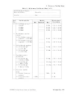
Страница 108: ...ustomer Tested by Ambient temperature C Relative humidity Power main line frequency Hz nominal Test Equipment Used Description Model No Trace No Cal Due Date Host spectrum analyzer Measuring receiver Power sensor Microwave spectrum analyzer Frequency counter Power splitter Special notes HP 85640A RF Tracking Generator Operation and Service Manual Performance T ests 4 35 ...

Страница 109: ...imum step to step attenuator accuracy 010 dB 00 8 dB 0 8 dB 60 40 dB 020 dB 00 8 dB 0 8 dB 60 41 dB 030 dB 00 8 dB 0 8 dB 0 11 00 12 dB 040 dB 00 8 dB 0 8 dB 0 13 00 14 dB 050 dB 00 8 dB 0 8 dB 60 15 dB 060 dB 00 8 dB 0 8 dB 60 16 dB 070 dB 00 8 dB 0 8 dB 0 17 00 18 dB 2 Maximum leveled output power 13 Maximum leveled 0 dBm 60 46 dB output power 3 Level atness 14 Maximum atness 2 0 dB 60 41 dB 15 ...

Страница 110: ...MHz 027 dBc 1 55 01 80 dB 27 Non harmonic response amplitude 2000 MHz 023 dBc 3 45 04 01 dB 6 LO feedthrough amplitude 11 LO feedthrough 026 dBm 2 02 02 50 dB at 3 911 GHz 16 LO feedthrough 026 dBm 2 10 02 67 dB at 6 8107 GHz 7 Tracking generator feedthrough 13 TG feedthrough 095 dBm 1 74 01 98 dB 300 kHz to 1 MHz 14 TG feedthrough 0115 dBm 1 74 01 98 dB 1 MHz to 2 GHz 15 TG feedthrough 0110 dBm 1...

Страница 111: ......

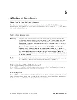
Страница 112: ... printed circuit board remove the instrument s line power cord Capacitors inside the instrument may still be charged even if the instrument has been disconnected from its source of supply Use a nonmetallic adjustment tool whenever possible Note Before beginning the adjustment procedures allow the instrument to warm up for at least ve minutes see General Speci cations in Table 1 1 Which Adjustment ...

Страница 113: ...citors and slug tuned inductors Refer to Table 4 1 for any other required service accessory part numbers Table 5 1 Adjustment Procedures and Equipment Used Adjustment Number Adjustment Name Equipment Used 1 Power supply adjustments and checks Digital voltmeter 2 600 MHz level adjustment Host spectrum analyzer 3 Power level adjustments Host spectrum analyzer Power sensor Measuring receiver Digital ...

Страница 114: ...rence Designator Adjustment Name Adjustment Number Adjustment Description 15V ADJ 15V ADJ 1 Adjusts the 15 V dc supply voltage 015V ADJ 015V ADJ 1 Adjusts the 015 V dc supply voltage A2C3 TRACK OSC 4 Sets center frequency of tracking oscillator A3R1 COR TRACK 4 Coarse adjustment of TUNE voltage to tracking oscillator A3R2 S T GAIN 3 Adjusts gain of sweep plus tune voltage for slope atness compensa...

Страница 115: ...pply but the measurements are made on the A3 interface assembly Other voltages on the interface assembly are also checked Caution The tracking generator assemblies are static sensitive Perform this adjustment procedure at a static safe workstation Refer to Figure 7 1 for an example of a static safe workstation Figure 5 1 Power Supply Adjustments and Checks Setup 5 4 Adjustment Procedures HP 85640A...

Страница 116: ...1 Power Supply Adjustments and Checks Figure 5 2 Power Supply Adjustments and Test Point Locations HP 85640A RF Tracking Generator Operation and Service Manual Adjustment Procedures 5 5 ...

Страница 117: ...o ON 4 Set the DVM controls as follows FUNCTION DC VOLTS RANGE 100 VOLTS 5 Locate 15V ADJ see Figure 5 1 Adjust 15V ADJ for a DVM reading of 15 V 60 05 V 6 Remove the positive test lead from the DVM from A3C27 Connect it to the negative end of A3C28 the end labeled 015V See Figure 5 2 7 Locate 015V ADJ see Figure 5 1 Adjust 015 V ADJ for a DVM reading of 015 V 60 05 V 8 Connect the positive test l...

Страница 118: ... level at A3J5 to 08 dBm 61 dB The host spectrum analyzer s CAL OUTPUT amplitude is checked rst The level of undesired harmonics at A3J5 are also checked Caution The tracking generator assemblies are static sensitive Perform this adjustment procedure at a static safe workstation Refer to Figure 7 1 for an example of a static safe workstation Figure 5 3 600 MHz Level Adjustment Setup HP 85640A RF T...

Страница 119: ...ter 7 Place the tracking generator in the service position See Figure 5 3 2 Disconnect W5 from A3J5 see Figure 5 4 Turn the tracking generator LINE switch ON 3 Check the host spectrum analyzer s CAL OUTPUT amplitude using the appropriate performance test in the spectrum analyzer s installation and veri cation manual If the amplitude does not meet the speci cation correct the problem before continu...

Страница 120: ...d record the marker amplitude reading below Initial 600 MHz amplitude dBm 10 Calculate the amount of di erence in attenuation required to set the amplitude to 08 dBm as indicated below Round the calculated value to the nearest whole number attenuation di erence initial 600 MHz amplitude 8 dBm Attenuation di erence rounded dBm 11 If the attenuation di erence rounded is 61 dB disconnect the BNC cabl...

Страница 121: ... the step keys to set the spectrum analyzer to each of the center frequencies listed in Table 5 6 At each frequency setting press 4PEAK SEARCH5 and record the marker amplitude in Table 5 6 for the appropriate frequency The marker amplitude should be less than the speci cation listed 17 Replace the BNC cable at A3J5 with the W5 cable Table 5 5 Attenuation Values of Pad A3U4 HP Part Number Manufactu...

Страница 122: ... 6 Harmonic and Subharmonic Levels Frequency MHz Marker Amplitude dBc Speci cation dBc 300 025 900 025 1200 010 1500 025 1800 010 2100 025 2400 010 HP 85640A RF Tracking Generator Operation and Service Manual Adjustment Procedures 5 11 ...

Страница 123: ...itry is adjusted to yield 010 dBm at the 0 dBm vernier setting and 020 dBm at the 010 dBm vernier setting the OUTPUT LEVEL attenuator is set to 010 dB The sweep plus tune gain S T GAIN is adjusted for the same amplitude at 2 9 GHz as at 300 MHz Caution The tracking generator assemblies are static sensitive Perform this adjustment procedure at a static safe workstation Refer to Figure 7 1 for an ex...

Страница 124: ...A Procedure 1 Remove the tracking generator cover refer to Removing and Replacing the Instrument Cover in Chapter 7 Connect the equipment as shown in Figure 5 5 with the Type N cable connected between the tracking generator RF OUTPUT and the host spectrum analyzer INPUT 50 connectors Set the LINE switch to ON 2 Connect the positive DVM test lead to A3TP4 and the negative DVM test lead to the negat...

Страница 125: ...ectrum analyzer is an HP 8560A E HP 8561B E or HP 8563A E press 4AUX CTRL5 NNNNNNNNNNNNNNNNNNNNNNNNNNNNNNNN REAR PANEL NNNNNNNNNNNNNNNNNNNNNNNNNNNNNNNNNNNNNNNNNNNNNNN 0 5 V GHz FAV 10 Adjust TRACKING ADJUST to display a maximum signal level on the host spectrum analyzer screen 11 Zero and calibrate the measuring receiver and power sensor Enter the power sensor s 300 MHz Cal Factor into the measuri...

Страница 126: ...form this adjustment only if the tracking adjustment range performance test has failed This adjustment centers the tracking oscillator range Typically performing the ne adjustment on the A3 interface assembly is su cient In some cases however adjusting the A2 tracking generator coarse adjustment is necessary The coarse adjustment A2C3 is rated for a maximum of 10 adjustment cycles Because of this ...

Страница 127: ... f 1250 1476 Procedure 1 Remove the cover from the tracking generator refer to Removing and Replacing the Instrument Cover in Chapter 7 Connect the equipment as shown in Figure 5 7 Also connect a BNC cable between the frequency counter FREQ STD OUT and the host spectrum analyzer 10 MHz REF IN OUT Set the tracking generator LINE switch to ON and allow it to warm up for at least 10 minutes 2 Press 4...

Страница 128: ...e of the frequency noted in step six above 6100 Hz 9 Repeat steps six through eight at least once more until the absolute values of the counter readings with the TRACKING ADJUST control fully clockwise and fully counterclockwise are within 500 Hz of each other If the absolute values of the counter readings cannot be set to within 500 Hz of each other continue with step 11 to check the absolute tra...

Страница 129: ...justment cycles Because of this limitation adjust A2C3 only when absolutely necessary 19 Adjust A2C3 until the frequency counter reads 300 MHz 6500 Hz 20 Repeat steps 15 through 19 at least once more until no further adjustment of A2C3 is necessary 21 Set the tracking generator LINE switch to OFF Replace A2 dust cap screw 22 Repeat the ne adjustment procedure steps four through 12 Table 5 7 Tracki...

Страница 130: ...nerator are listed in tables some with accompanying illustrations in this chapter Rebuilt exchange assembly part numbers are included here as well Refer to Chapter 7 for replacement procedures and the rebuilt exchange assembly procedure HP 85640A RF Tracking Generator Operation and Service Manual Assembly Replaceable Parts 6 1 ...

Страница 131: ... A A5W3 cable assembly grounding 5062 1903 1 A5W2S1 switch DPST 3101 2905 7 AT1 50 terminator 1810 0118 1 W1 cable assembly front panel controls 85640 60002 6 W2 cable assembly tracking generator drive 8120 4157 0 W3 cable assembly EXT ALC input 08560 60001 6 W4 cable assembly 300 MHz input 85640 60008 2 W5 cable assembly 600 MHz input 85640 60007 1 W6 cable assembly blanking input 85640 60009 3 W...

Страница 132: ...Figure 6 1 Major Assemblies and Cable Locations HP 85640A RF Tracking Generator Operation and Service Manual Assembly Replaceable Parts 6 3 ...

Страница 133: ...Lock washer 0 384 in ID 2190 0022 1 8 Hex nut 3 8232 mm 2950 0001 8 9 Knob round 75 jade gray 0370 3215 0 10 Set screw 125 in 3030 0007 5 11 Bulkhead connector type N f 1250 2191 6 12 Hex nut 15 32232 mm 0590 1251 6 13 W4 cable assembly 300 MHz IN 85640 60008 5 14 Not assigned 15 Hex nut 3 8232 mm 2950 0001 8 16 Lock washer 314 in ID 2190 0033 4 17 Adapter SMA f to SMA f 1250 1666 8 Figure 6 2 Mec...

Страница 134: ...mm ID 2190 0583 9 32 O ring 0 070 in ID 0905 0375 2 33 Screw 3 028 mm athead 0515 1459 8 34 Screw 3 026 mm panhead 0515 1146 0 35 Hook and loop fastener 0510 1303 1 36 Screw 3 028 mm panhead 0515 1079 8 37 Screw 3 028 mm athead 0515 1459 8 38 Screw 4 028 mm athead 0515 1367 7 39 Hex nut with lock washer 4 mm 0535 0082 3 40 Screw 3 0210 mm athead 0515 1460 1 41 Flat washer 2 5 mm ID 3050 0890 6 42 ...

Страница 135: ...Figure 6 3 Mechanical Replaceable Parts 2 of 2 6 6 Assembly Replaceable Parts HP 85640A RF Tracking Generator Operation and Service Manual ...

Страница 136: ...t to do if you have a problem with the tracking generator You ll also nd A system level block diagram An instrument level block diagram An instrument level wiring diagram An A3 interface assembly component level replaceable parts list An A3 interface assembly component location diagram An A3 interface assembly schematic diagram HP 85640A RF Tracking Generator Operation and Service Manual Service I...

Страница 137: ...ctronic Components Caution Handle these items only at a static safe work station Store or transport these items only in static shielding containers Personnel should be grounded with a resistor isolated wrist strap before touching any connector pins or before removing any assembly from the instrument Be sure that all instruments are properly earth grounded to prevent buildup of static charge 7 2 Se...

Страница 138: ...rist strap and wrist strap cord are not included They must be ordered separately 9300 0980 Wrist strap cord 1 5 m 5 ft 9300 1383 Wrist strap black stainless steel without cord has four adjustable links and a 7 mm post type connection 9300 1169 ESD heel strap reusable 6 to 12 months HP 85640A RF Tracking Generator Operation and Service Manual Service Information 7 3 ...

Страница 139: ...e carton Pellets cause equipment damage by generating static electricity 3 Use the original materials see Figure 7 2 or a strong shipping container of double walled corrugated cardboard with 159 kg 350 lb bursting strength The carton must be large enough and strong enough to accommodate the instrument and to allow at least three to four inches on all sides of the instrument for packing material 4 ...

Страница 140: ...ls Item HP Part Number Description 1 Outer carton 9211 6065 2 Front foam pad 9220 4620 3 Bottom tray 9220 4621 4 Rear foam pad 9220 4622 5 Anti static vinyl bag large 85901 80002 HP 85640A RF Tracking Generator Operation and Service Manual Service Information 7 5 ...

Страница 141: ...d tested are available only on a trade in basis therefore the defective assembly must be returned for credit To return a defective exchange assembly 1 Record the nature of the assembly s defect 2 Wrap the defective assembly in its static safe wrapping and replace it in the original shipping container Enclose a copy of the recorded defect information 3 Place the pre addressed label on the package a...

Страница 142: ...in the rear bumper feet These feet are secured to the instrument cover assembly It is not necessary to remove them now 4 Pull the instrument cover toward the rear of the tracking generator to remove it Replacement 5 Turn the cover assembly so the vent holes are on the bottom of the tracking generator With the tracking generator sitting on its front panel slide the instrument cover assembly onto th...

Страница 143: ...nuator shaft adapter forward as far as it can go 4 Remove the two screws 5 holding the attenuator to the attenuator bracket Replacement 5 Rotate the attenuator shaft fully clockwise 6 Connect the replacement attenuator to the attenuator bracket by replacing and start tightening the two screws 5 7 Replace the attenuator adapter and secure it with the two allen screws 4 8 Move the attenuator to alig...

Страница 144: ...Figure 7 3 A1 Attenuator Replacement HP 85640A RF Tracking Generator Operation and Service Manual Service Information 7 9 ...

Страница 145: ...J2 3 W8 from A2J4 4 W3 from A2J6 5 W5 from A2J8 3 Rotate the instrument onto its front panel Hold the A2 tracking generator as you remove the three screws 6 that attach it to the chassis Replacement 4 Orient A2 with A2J2 A2J3 and A2J4 facing toward the front of the instrument 5 Attach A2 to the instrument chassis with the three screws 6 tightened to six inch pounds 6 Replace the following ve cable...

Страница 146: ...Figure 7 4 A2 Tracking Generator Assembly Replacement HP 85640A RF Tracking Generator Operation and Service Manual Service Information 7 11 ...

Страница 147: ...e hook and loop fastener then lift the board assembly from the instrument Replacement 5 If you are replacing the bottom shield or installing a new board assembly attach either the hook or loop side to the bottom shield so it aligns with the fastener remaining on the chassis 6 Replace the top and bottom shields to the A3 board assembly then tighten the six screws 9 7 Align the A3 board assembly in ...

Страница 148: ...Figure 7 5 A3 Interface Board Assembly Replacement HP 85640A RF Tracking Generator Operation and Service Manual Service Information 7 13 ...

Страница 149: ...rame 7 Desolder the two wires 7 on the ALC switch making note of the proper connections Lift the switch out of its slot 8 Clip the two cable ties 8 to free A4W2 cable assembly and disconnect it from A3J3 9 9 Remove the four screws A and B that secure the power supply bracket to the chassis Lift the power supply assembly out of the instrument Replacement 10 Replace the A4 power supply in the chassi...

Страница 150: ...Figure 7 6 A4 Power Supply Replacement HP 85640A RF Tracking Generator Operation and Service Manual Service Information 7 15 ...

Страница 151: ...Carefully pull A5W2 7 out of the harness clips 8 and remove the A5 assembly Replacement 10 Replace the line module into the chassis with the plug prongs toward the top of the tracking generator and the voltage selection switch toward the bottom Alternately tighten the two screws 5 11 Reconnect A5W3 grounding wire with the nut 4 and tighten it to six inch pounds 12 Lay A5W2 7 along its path near th...

Страница 152: ...Figure 7 7 A5 FL1 Line Filter Module Replacement HP 85640A RF Tracking Generator Operation and Service Manual Service Information 7 17 ...

Страница 153: ... is always greater than the tuned frequency by 3 9107 GHz the 1st IF and the tracking generator mixes this 1st LO signal with 3 9107 GHz the tracking generator output frequency will be the same as the host spectrum analyzer s tuned frequency The spectrum analyzer s 1st IF does not need to be exactly 3 9107 GHz as long as the tracking generator s 1st IF is equal to the 1st IF of the host spectrum a...

Страница 154: ...eveled externally by using a negative polarity crystal detector A rear panel switch on the tracking generator can be used to select between internal and external leveling The EXT ALC INPUT connector on the rear panel routes the detector output directly to the A2 tracking generator assembly Figure 7 8 Simpli ed HP 85640A to Host Spectrum Analyzer System Block Diagram HP 85640A RF Tracking Generator...

Страница 155: ...Figure 7 9 Simpli ed HP 85640A RF Tracking Generator Block Diagram 7 20 Service Information HP 85640A RF Tracking Generator Operation and Service Manual ...

Страница 156: ...uency to compensate for the frequency inaccuracies of the host spectrum analyzer s 10 7 MHz IF The tracking oscillator determines the residual FM and frequency drift of the tracking generator The 182 14 MHz output frequency is obtained by doubling the output of a crystal oscillator operating at 91 07 MHz Upconverter The upconverter mixes the tracking oscillator output with the 600 MHz signal comin...

Страница 157: ... s 300 MHz notch lter eliminates the 300 MHz fundamental signal Power level control The power level of the A2 tracking generator is controlled by both the front panel OUTPUT LEVEL vernier and the rear panel 0 5V GHz INPUT from the host spectrum analyzer The 0 5V GHz INPUT provides slope atness compensation to the output power level Unlevel detector The A2 tracking generator provides the ALC MON AL...

Страница 158: ...line lter switch assembly consists primarily of A5FL1 the line lter module and A5W2S1 the instrument line switch A5FL1 line lter module lters incoming ac power fuses the power line side of the ac power and sets the proper transformer taps on the A4 power supply for the required line voltage A spare fuse is included in the line lter module The instrument line switch switches both the line and neutr...

Страница 159: ...er to zero span and a 5 second sweep time b Step the center frequency in 50 MHz increments c Note and record which frequencies cause the unleveled condition 2 Determine which power levels cause the unleveled condition a Connect the tracking generator s RF OUTPUT to the host spectrum analyzer s INPUT 50 b Set the host spectrum analyzer to zero span and CENTER FREQ to 300 MHz or to one of the freque...

Страница 160: ...EQ setting s that caused an unleveled condition suspect either A2 or W8 6 If the output is unleveled only at certain power level settings or certain frequencies monitor A3U5 pin 1 with a digital voltmeter DVM a Connect the negative DVM lead to the negative end of A3C27 b Vary the tracking generator OUTPUT LEVEL vernier or host spectrum analyzer CENTER FREQ settings as appropriate and plot the volt...

Страница 161: ...oint should be greater than 500 mV If the voltage is less than 500 mV perform the tracking oscillator range performance test in Chapter 4 of this manual c If the instrument fails this test perform the tracking oscillator range adjustment in Chapter 5 of this manual d If noise on this tune line is greater than 10 mV examine the tracking control circuitry on A3 3 Monitor the output of the tracking g...

Страница 162: ... LO OUTPUT amplitude performance test for the host spectrum analyzer b If the spectrum analyzer passes this test the fault most likely is with the A2 tracking generator c If the spectrum analyzer fails this test determine the equivalent CENTER FREQ setting at which the power level was out of tolerance by subtracting 3 9107 from the 1st LO frequency Compare the result with the frequency ies at whic...

Страница 163: ...NNNNNNNNNNNNNNNNNNNNNNNNNNNNNNN FREQ DIAGNOSE NNNNNNNNNNNNNNNNNNNNNNN LO FREQ 5 The frequency displayed is the 1ST LO OUTPUT fundamental frequency Use the HP 8566A B to measure the 1st LO signal s second and third harmonics levels Note The 1st LO typically has a higher harmonic content than does the tracking generator output For this check the variation in harmonic content versus frequency is the ...

Страница 164: ... drive or LO INPUT 2 If the sidebands on the output disappear when using the clean signal the substituted signal is responsible for the sidebands Note The 600 MHz drive signal should be 08 dBm 63 5 dB The 1st LO signal should be 16 dBm 62 dB HP 85640A RF Tracking Generator Operation and Service Manual Service Information 7 29 ...

Страница 165: ...g adjustment controls Monitor A3U5 pin 8 with a DVM Rotate the TRACKING ADJUST control from fully counterclockwise to fully clockwise The voltage measured should increase from 0 V to 8 V Caution The following step requires adjustment of A2C3 The lifetime of A2C3 is rated for less than 10 cycles Do not adjust A2C3 unless it is absolutely necessary 6 If all the above checks are acceptable then the t...

Страница 166: ...ror messages ERR 902 BAD NORM 3 18 ERR 903 A DLMT 3 20 SAVELOCK ON 3 17 3 27 3 35 3 40 ext alc input 3 4 F atness out of tolerance 7 27 frequency tracking range performance test 4 31 front panel features 3 2 front panel interconnections 3 2 G general information calibration cycle 1 4 characteristics 1 11 serial numbers 1 4 speci cations 1 6 H harmonic spurious outputs performance test 4 16 host sp...

Страница 167: ...3 4 rear panel interconnections 3 4 rear panel sweep output 4 3 reference trace 3 15 3 26 re ection measurement example HP 8560A E HP 8561B E HP 8563A E 3 30 HP 8561A HP 8562A B 3 37 savelock on error 3 35 3 40 store open short average reference 3 32 replacement procedures 7 6 17 A5 line lter switch assembly replacement 7 16 replacing A1 attenuator 7 8 replacing A2 tracking generator 7 10 replacin...

Страница 168: ...or feedthrough performance test 4 27 tracking generator host spectrum analyzer connections 3 5 transmission measurement example adjusting the range level 3 18 3 28 calibration HP 8561A or HP 8562A B 3 15 3 26 HP 8560A E HP 8561B E HP 8563A E 3 9 HP 8561A HP 8562A B 3 21 savelock on error 3 17 3 27 storing thru reference 3 17 3 27 troubleshooting 7 24 30 block diagram 7 18 excessive FM 7 26 harmoni...

Страница 169: ......

Отзывы: