40
8.3
RE-ASSEMBLY 163 COMPRESSOR AFTER OVERHAUL (Continued)
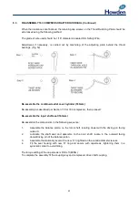
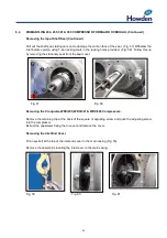
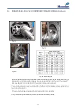
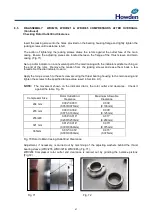
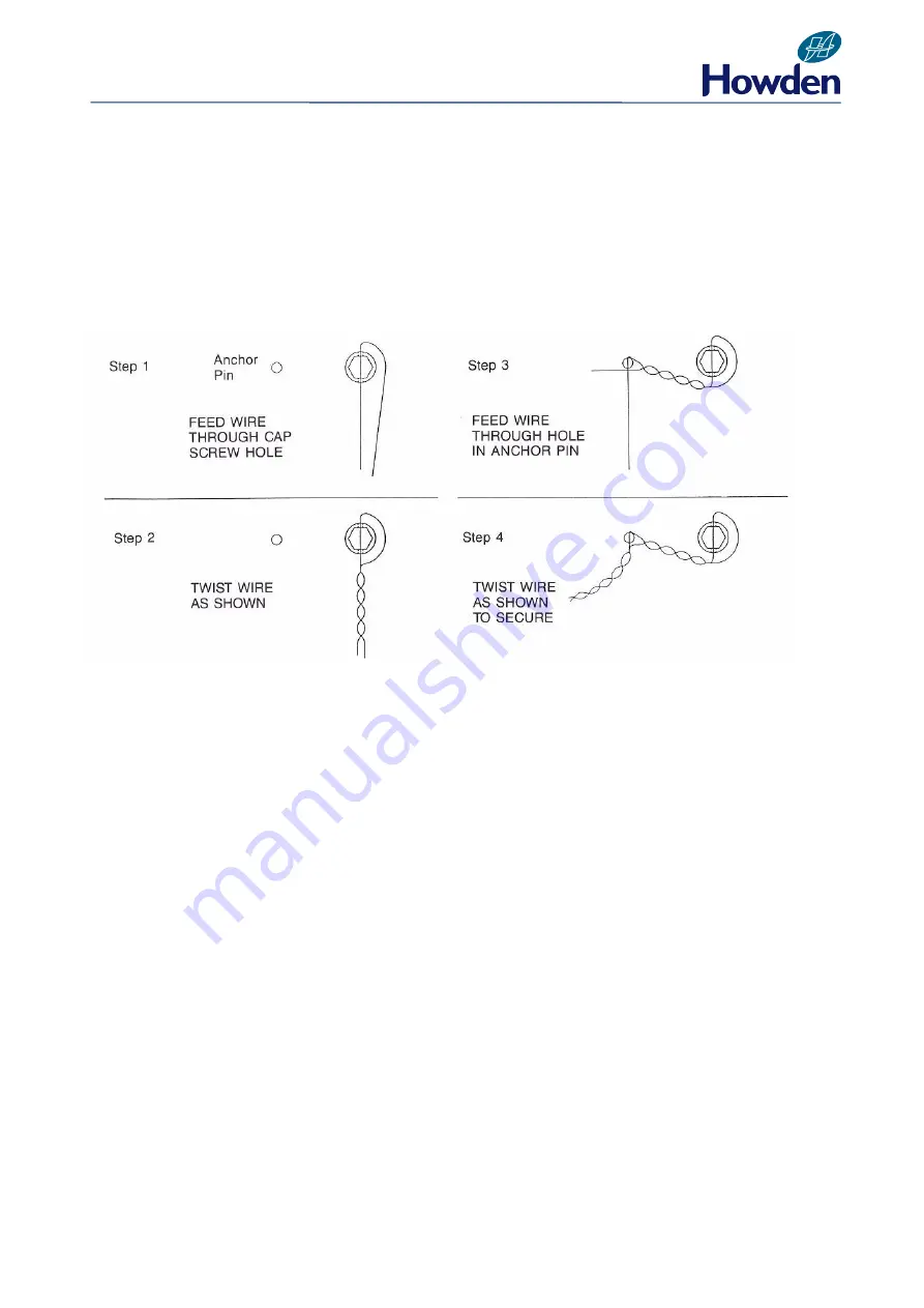
When the clearances are finalised, the retaining cap screws on the Thrust Retaining Plate should be
wire locked using the following method:
The grade of wire used should be 1/16” diameter Annealed S.S. Safety Wire.
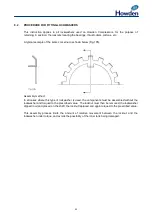
Adjustment, if necessary, is carried out by machining of the adjusting plate behind the thrust
bearings (Fig. 52).
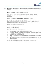
Re-assemble the combined outlet cover/cylinder (163mm)
Re-assembly as described per Section 7.5 for 163 compressor, then proceed:
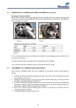
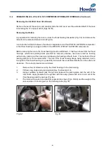
Re-assemble the input shaft seal (163mm)
Re-assemble the components in the following sequence:
1.
Assemble the balance piston on the rotor shaft, locating dowel with the driving pin facing
outward.
2.
Lubricate the shaft seal and assemble to the rotor shaft, locate in the outward facing
dowel/driving pin of the balance piston.
3.
Assemble the stationary seat with a new ‘O’ ring fitted on the outside diameter recess.
4.
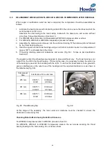
Fit the seal housing with new ‘O’ ring and secure with capscrews, tightening them in a
systematic order to avoid tilting.
The torque setting of the cap screws is 35lbs ft (48Nm).
To complete the assembly fit the coupling key and compressor driven half coupling.
Содержание WRV
Страница 1: ...WRV WRVi COMPRESSOR RANGE SERVICE MANUAL...
Страница 3: ...2 SECTION 1 FOREWORD...
Страница 5: ...4 HOWDEN SECTION 2 DESCRIPTION...
Страница 10: ...9 SECTION 3 INSTALLATION...
Страница 14: ...13 SECTION 4 FIRST START UP...
Страница 16: ...15 SECTION 5 NORMAL OPERATION...
Страница 18: ...17 SECTION 6 PROCEDURES DURING SHUTDOWN...
Страница 20: ...19 SECTION 7 MAINTENANCE...
Страница 33: ...32 SECTION 8 OVERHAUL...
Страница 50: ...49 SECTION 9 SPECIAL INSTRUCTIONS...
Страница 57: ...56 SECTION 10 SPARES...
Страница 64: ...63 Printed in the UK Issue HCL September 2012 Howden Compressors Limited...

