39
8.3
RE-ASSEMBLY 163 COMPRESSOR AFTER OVERHAUL (Continued)
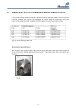
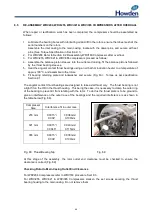
Checking Rotor to main casing Outlet End Clearance (163mm)
1.
Remove the thrust retaining plate (if fitted).
2.
The adjusting plate behind the thrust bearings has two lugs with tapped holes for withdrawal
purposes.
3.
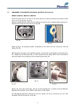
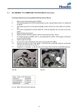
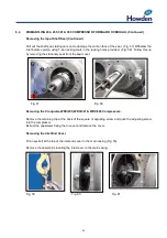
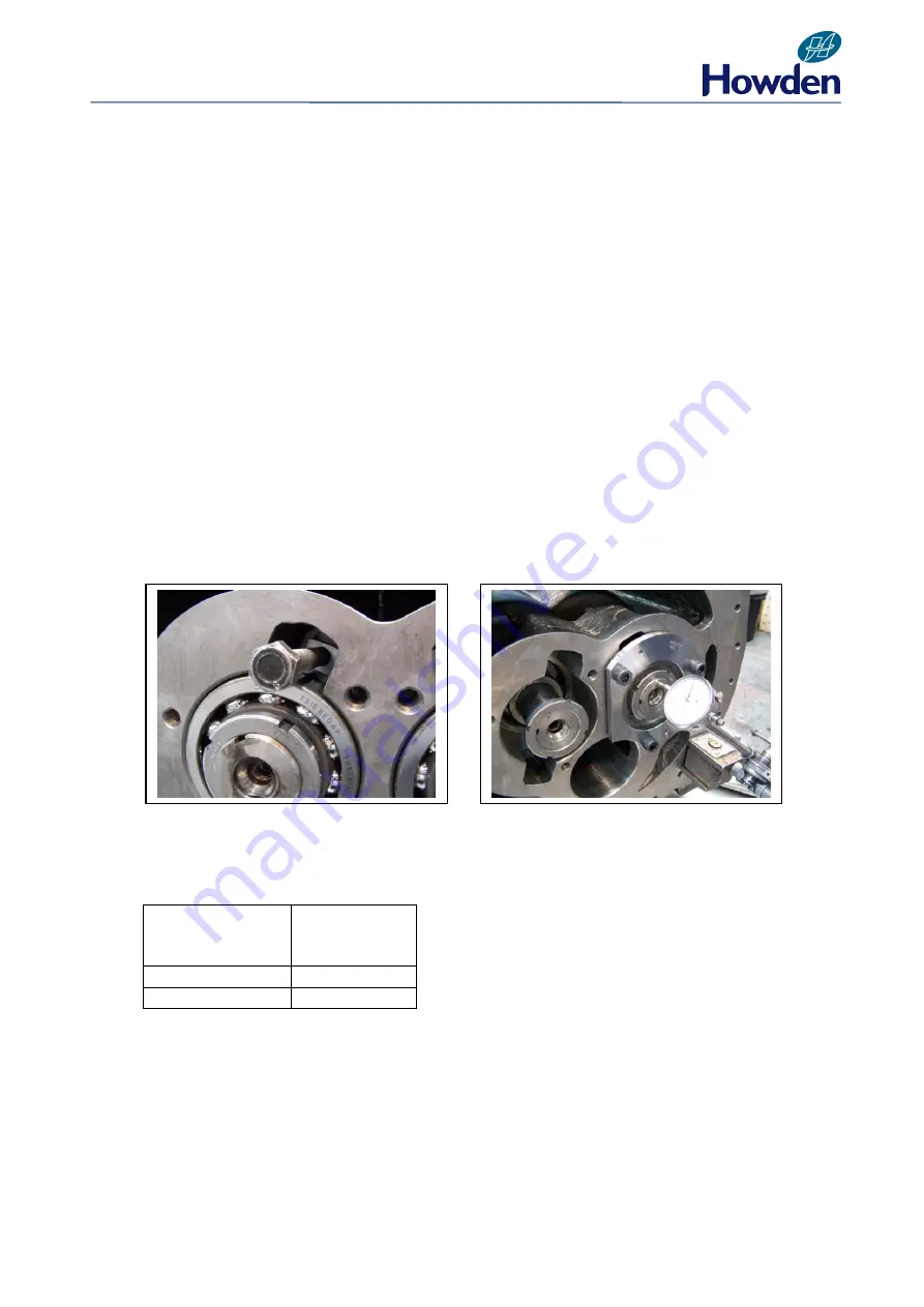
Insert jacking screws into the lugs and lightly tension the screws until resistance if felt (Fig.
49).
4.
The action of tightening the screws draws the rotors hard against the outlet end of the main
casing.
5.
Remove the jacking screws.
6.
Replace the thrust retaining plate and the retaining screws (Figs. 33-34).
7.
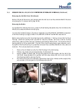
Fit a clock gauge in a suitable point on the casing with the spindle of the gauge touching the
end of the rotor (Fig 50).
8.
Set the clock dial to zero.
9.
Torque up the plate retaining screws using a torque wrench to 14Nm.
10.
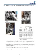
Note the movement on the clock gauge. This is the rotor outlet end clearance and should
correspond to the table as per Fig. 51.
11.
Adjustment, if necessary, is carried out by machining of the thrust bearing withdrawal plates.
Fig. 49
Fig. 50
Rotor Outlet End
Clearance
163 Compressor
Maximum
Allowable
Clearance
0.050/0.075mm
0.100mm
0.002/0.003”
0.004”
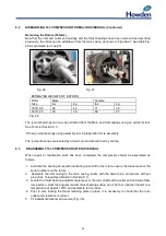
Fig. 51 WRV 163 Outlet End Clearance
Содержание WRV
Страница 1: ...WRV WRVi COMPRESSOR RANGE SERVICE MANUAL...
Страница 3: ...2 SECTION 1 FOREWORD...
Страница 5: ...4 HOWDEN SECTION 2 DESCRIPTION...
Страница 10: ...9 SECTION 3 INSTALLATION...
Страница 14: ...13 SECTION 4 FIRST START UP...
Страница 16: ...15 SECTION 5 NORMAL OPERATION...
Страница 18: ...17 SECTION 6 PROCEDURES DURING SHUTDOWN...
Страница 20: ...19 SECTION 7 MAINTENANCE...
Страница 33: ...32 SECTION 8 OVERHAUL...
Страница 50: ...49 SECTION 9 SPECIAL INSTRUCTIONS...
Страница 57: ...56 SECTION 10 SPARES...
Страница 64: ...63 Printed in the UK Issue HCL September 2012 Howden Compressors Limited...

