31
7.5
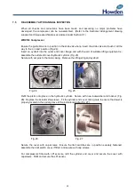
REASSEMBLY PROCEDURE FOR ANNUAL INSPECTION (Continued)
WRV204, WRVi255, WRVi321 & WRVi365
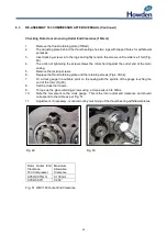
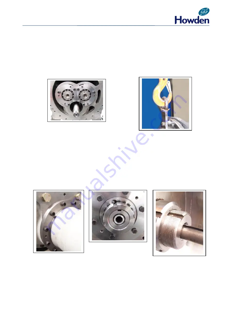
Ensure the guide block is in position in the slide valve bore, insert the slide valve and push it all the
way to the on load position (Fig. 28).
Insert an eyebolt into the outlet end cover flange and with the aid of suitable lifting equipment re-
assemble the outlet end cover and secure (Fig. 29).
Fig. 28
Fig. 29
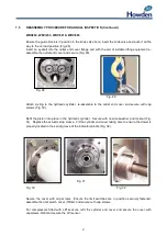
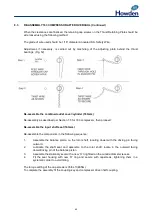
Attach a sling to the hydraulic cylinder, re-assemble to the outlet end cover and secure with cap
screws (Fig. 30).
Refit the piston into place in the hydraulic cylinder. Secure with new lockwasher and locknut (Fig.
31). Replace the actuator stop sleeve. Fit the cylinder end cover taking care to ensure the dowel is
properly located in the spiral groove of the indicator spindle (Fig
.
32).
Fig. 31
Fig. 30
Fig. 32
Secure the cover with cap screws. Ensure the limit switches are in position securely fastened,
assemble the limit switch cover, if fitted, and secure with cap screws.
For compressors fitted with LPI sensors, refit the cylinder end cover and secure the cover with
capscrews. Refit and secure the LPI sensor.
Содержание WRV
Страница 1: ...WRV WRVi COMPRESSOR RANGE SERVICE MANUAL...
Страница 3: ...2 SECTION 1 FOREWORD...
Страница 5: ...4 HOWDEN SECTION 2 DESCRIPTION...
Страница 10: ...9 SECTION 3 INSTALLATION...
Страница 14: ...13 SECTION 4 FIRST START UP...
Страница 16: ...15 SECTION 5 NORMAL OPERATION...
Страница 18: ...17 SECTION 6 PROCEDURES DURING SHUTDOWN...
Страница 20: ...19 SECTION 7 MAINTENANCE...
Страница 33: ...32 SECTION 8 OVERHAUL...
Страница 50: ...49 SECTION 9 SPECIAL INSTRUCTIONS...
Страница 57: ...56 SECTION 10 SPARES...
Страница 64: ...63 Printed in the UK Issue HCL September 2012 Howden Compressors Limited...

