background image


READ CAREFULLY BEFORE INSTALLING AND STARTING YOUR COMPRESSOR 

 
These instructions have been prepared to ensure that your compressor gives long and satisfactory service. 
 
Detailed instructions for carrying out an annual inspection or overhaul procedure is included for the following 
range of compressors: 
 
MK1G-1K/WRV163 
 
MK6-6D/WRV204 
 
MK6-6D/WRVi255 
 
MK6-6C/WRVi321 
 
MK1/WRVi365 
 
The entire manual should be read before reverting to any one section for specific information.   
 
One copy should be given to the personnel responsible for installing and operating the compressor. 
 
All requests for information, services or spares should be directed to: 
 

HOWDEN COMPRESSORS     

or 

Compressor Business Unit  
133 Barfillan Drive 
Glasgow  
G52 1BE  
UK 
 
Telephone:  0044 (0)141 882 3346    
Fax:             0044 (0)141 882 8648 
E-mail:         [email protected] 
Website:      www.howden.com 


All  enquiries  should  be  accompanied  by  the  Howden  Compressors  Contract  Number  and  the  Compressor 
Serial Number, taken from the nameplate on the side of the compressor body. 


HOWDEN 

COMPRESSORSCOMPRESSORS 


HOWDEN COMPRESSORS LLC 

1850B North Gravers Road 
Plymouth Meeting 
PA 19462 
USA 
 
 
Telephone:   001 610 313 9800 
Fax:              001 610 313 9215 
E-mail:         [email protected]


Website:       www.howden.com


Содержание WRV

Страница 1: ...WRV WRVi COMPRESSOR RANGE SERVICE MANUAL...

Страница 2: ...ual Inspection 21 7 3 Dismantling Procedure for Annual Inspection 21 7 4 Checking Clearances 28 Guide Block 28 Thrust Bearing 29 7 5 Re assembly after Annual Inspection 30 SECTION 8 OVERHAUL 32 8 1 Ge...

Страница 3: ...2 SECTION 1 FOREWORD...

Страница 4: ...responsible for installing and operating the compressor All requests for information services or spares should be directed to HOWDEN COMPRESSORS or Compressor Business Unit 133 Barfillan Drive Glasgo...

Страница 5: ...4 HOWDEN SECTION 2 DESCRIPTION...

Страница 6: ...ameter Each rotor is supported by two plain white metal thick walled journal bearings fitted adjacent to the compression chamber Angular contact bearings offloaded by internal balance pistons accommod...

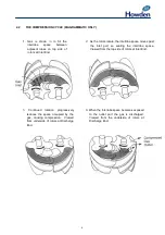
Страница 7: ...pace moves past the inlet port so sealing the interlobe space Viewed from the top side of rotors at Inlet End 4 When the interlobe space becomes exposed to the outlet port the gas is discharged Viewed...

Страница 8: ...ay also be fitted where a very high separation efficiency is required The oil separated is usually drained into the compressor through a small bore pipe which can be fitted with a protective filter an...

Страница 9: ...al Standard Refrigerants R717 R22 R134a R404A R407C R410A R507 Typical Oils Mineral Oil Polyol Ester Oil Poly Alkylene Glycol Oil Alkyl Benzene Oil Oil Viscosity For the majority of ammonia refrigerat...

Страница 10: ...9 SECTION 3 INSTALLATION...

Страница 11: ...pling gap radial and facial alignment will only require movement of one unit on the existing shim size Coupling gap dimensions should be set with the couplings held in a repeatable position ie hard to...

Страница 12: ...t located axially or preferably by a double clock method which avoids the problem of repeated axial position 3 2 ALIGNMENT TOLERANCE The maximum acceptable line up tolerance for couplings on compresso...

Страница 13: ...tion thread is BSP and so a 1 OD pipe should be used NOTE All piping should be supported so that no strain is transmitted to the compressor casings The piping should be inspected for cleanliness befor...

Страница 14: ...13 SECTION 4 FIRST START UP...

Страница 15: ...ve unit disconnected from the compressor and mechanically operating the trips check that the actual settings are in accordance with the contract specification The lubricating oil differential pressure...

Страница 16: ...15 SECTION 5 NORMAL OPERATION...

Страница 17: ...Stop the drive unit 2 After the compressor stops the control system should be operated to move the slide valve into the off load position unless the control system does this automatically 3 After the...

Страница 18: ...17 SECTION 6 PROCEDURES DURING SHUTDOWN...

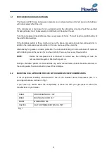
Страница 19: ...tion the normal lubricating oil can be drained off replaced with inhibiting oil and the set run for one hour initially then one hour every three months NOTE Before the compressor set is returned to no...

Страница 20: ...19 SECTION 7 MAINTENANCE...

Страница 21: ...ur years operation After this time the thrust bearings must be renewed When the compressor is being inspected or overhauled it must be dismantled in a clean area The inspection overhaul procedure is d...

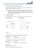
Страница 22: ...ts and condition of seals and guide block on the compressor during annual maintenance a certain amount of dismantling is required This differs slightly between the 163 compressor and the 204 255 321 3...

Страница 23: ...the spiral groove engaging the dowel pin is marked for correct re assembly to avoid damage to the potentiometer Move the slide valve to bring the actuator piston to the outer end of the cylinder Do no...

Страница 24: ...NNUAL INSPECTION Continued Removing the Combined Outlet Cover Cylinder 163 Compressor Fit an eyebolt to the tapped hole at the top of the outlet cover attach a sling to the eyebolt to support the weig...

Страница 25: ...cylinder Carefully draw the cover clear of the piston rod valve spindle Care should be taken to prevent damage to the actuator cylinder which is part of the cover At this stage the slide valve can be...

Страница 26: ...ve compressor and are removed as follows Removing the Hydraulic Cylinder Extract the cap screws or setscrews securing the cylinder to the end cover Fig 12 Support the cylinder with a sling and using t...

Страница 27: ...eight of the cover Fig 15 Remove the set pins locating the cover to the main casing and remove the cover Fig 15 Fig 16 Take care to avoid damage to the piston rod valve spindle Fig 16 Removing the Sli...

Страница 28: ...the valve bore a visual inspection of the rotors can be achieved Figs 18 19 Fig 18 Fig 19 PTFE Seals The compressor has now been dismantled enough to permit the inspection and replacement of the PTFE...

Страница 29: ...dimensions Guide Block to Slide Valve Slot Compressor Size by Rotor Diameter Dimension W Clearance 163 mm 24 987 24 975 mm 0 984 0 9833 0 046 0 013 mm 0 0018 0 005 204mm 29 987 29 975 mm 1 181 1 180...

Страница 30: ...ent of the thrust bearings the procedure for which is described per Section 8 2 8 3 or 8 4 8 5 NOTES It is extremely important that the fasteners on the thrust bearing retaining plates of the WRV163 a...

Страница 31: ...nt re assemble the outlet end cover hydraulic cylinder Fig 25 Secure with set pins to the main casing Remove the lifting sling and eyebolt Fig 24 Fig 25 Refit the piston into place in the hydraulic cy...

Страница 32: ...e to the outlet end cover and secure with cap screws Fig 30 Refit the piston into place in the hydraulic cylinder Secure with new lockwasher and locknut Fig 31 Replace the actuator stop sleeve Fit the...

Страница 33: ...32 SECTION 8 OVERHAUL...

Страница 34: ...location which should be a clean dry area where dismantling and assembly will take place Notes about Dismantling and Re assembly The dismantling and assembly method varies slightly between the WRV163...

Страница 35: ...moved Figs 33 34 Fig 33 Fig 34 Procure a piece of round bar 13mm diameter and approximately 14 355mm long Set up a dial indicator in a convenient position on the main casing to allow the spindle of th...

Страница 36: ...earance mm Drawing Clearance inches Maximum Allowable Clearance 163 0 070 0 1102 0 0028 0 0043 0 150mm 0 006 Fig 35 WRV163 Bearing Journal Clearances Carry on the dismantling procedure by unlocking th...

Страница 37: ...e shaft seal cover and using the jacking screw holes provided in conjunction with the T bar jacking tools remove the shaft seal cover Follow on with the removal of the Input Shaft Seal Assembly Figs 4...

Страница 38: ...e form of lifting gear Fig 43 Fig 43 Fig 44 Extract most of the screws securing the inlet cover to the main casing Remove the dowel pins locating the inlet cover to the main casing Fig 44 Remove the r...

Страница 39: ...wel pin and are retained by circlips 8 3 RE ASSEMBLY 163 COMPRESSOR AFTER OVERHAUL When repair or rectification work has been completed the compressor should be assembled as follows 1 Lubricate the be...

Страница 40: ...ing screws 6 Replace the thrust retaining plate and the retaining screws Figs 33 34 7 Fit a clock gauge in a suitable point on the casing with the spindle of the gauge touching the end of the rotor Fi...

Страница 41: ...pressor then proceed Re assemble the input shaft seal 163mm Re assemble the components in the following sequence 1 Assemble the balance piston on the rotor shaft locating dowel with the driving pin fa...

Страница 42: ...tates the use of a slightly different technique for measuring bearing lifts since there is no longer a hole in the rotor end in which to insert a lever to lift the rotor In this case the dial indicato...

Страница 43: ...existing bearings Compressor Size Drawing Clearance Maximum Allowable Clearance mm Inches 204 0 070 0 110 0 0028 0 0043 0 150mm 0 006 255 0 095 0 136 0 0037 0 0054 0 180mm 0 007 321 0 130 0 170 0 005...

Страница 44: ...is up by removing the stationary seat from the seal cover Fig 57 Fig 58 Removing the Vi adjuster WRVi255 WRVi321 WRVi365 Compressors Remove the retaining clip at the back of the square Vi adjusting sc...

Страница 45: ...provided for removal purposes have been used as bearing extractors by jacking out the housings and drawing the bearings off with them This method of thrust bearing removal is not recommended The risk...

Страница 46: ...5 891 405 Fig 67 Rotor Weights The thrust bearing sleeves and the angular contact thrust bearings can now be easily removed The balance piston and balance piston sleeves are now accessible and with th...

Страница 47: ...ining plate and lockwasher and secure Fig 63 Torque as per specification Section 9 1 The angular contact thrust bearings are designed to take axial thrust only The thrust bearing is not a tight fit on...

Страница 48: ...ro Apply the torque wrench to the set screw securing the thrust bearing housing to the main casing and tighten the screws to the specified torque value used in Section 9 1 NOTE The movement shown on t...

Страница 49: ...ing screw to cover NOTE Reset Vi adjusting screw to original position Re assemble the Input Shaft Seal Re assemble the component in the following sequence 1 Enter the inlet balance piston ensuring it...

Страница 50: ...49 SECTION 9 SPECIAL INSTRUCTIONS...

Страница 51: ...ng Capscrew Cylinder End Cover to Cylinder 88 120 G21015 5 8 x 2 Long Setscrew Superfeed Flange 80 108 Fig 74 Torque Specifications for Fasteners on WRV204 compressors PART NUMBER TYPE OF FASTENER TOR...

Страница 52: ...rew Stop Plate 37 50 G21039 5 8 UNC x 1 1 2 Long Setscrew Superfeed Flange 80 108 Fig 76 Torque Specifications for Fasteners on WRVi321 compressors PART NUMBER TYPE OF FASTENER TORQUE lb ft TORQUE Nm...

Страница 53: ...r 88 120 M0124100 M24 x 100 Long Set Screw Inlet and Outlet Casings 295 400 M0216045 M16 x 45 Long Vi Housing to Inlet 88 120 VR36149 2 45mm Locknut Piston Rod to Slide Valve 180 245 M0110030 M10 x 30...

Страница 54: ...Assembly method In all cases where this type of lockwasher is used the components must be assembled without the lockwasher and torqued to the prescribed value The locknut must then be removed the lock...

Страница 55: ...14T UNC 32436JC WRV204 Compressor Tools Part No Locknut Spanner 40mm for Piston Locknut 19187J Locknut Spanner 36mm 204 5009 Assembly Withdrawal Tool for Journal Bearings 204 5101 Jacking Plate for Ro...

Страница 56: ...xtractor Tool for Piston 32927J Thrust Bearing Assembly Tool 32928J Journal Bearing Assembly and Withdrawal Tool 32929J Jacking Screws for Thrust Housings 32994J Locknut Spanner for Coupling 32995J Lo...

Страница 57: ...56 SECTION 10 SPARES...

Страница 58: ...nspection Kit is required when changing the journal bearing or the thrust bearings For further information and details of the above please contact our Compressor Business Unit directly HOWDEN COMPRESS...

Страница 59: ...g G44001 O Ring Piston Rod 1 G44005 O Ring Actuator Spindle 1 G44006 O Ring Cylinder Cover 1 G44052 O Ring Main Inlet Outlet 2 G44053 O Ring Actuator Piston 1 G44054 O Ring Rotor Covers 2 G44055 O Rin...

Страница 60: ...t containing G44001 O Ring Piston Rod 1 G44005 O Ring Actuator Spindle 1 G44007 O Ring Actuator Piston 1 G44021 O Ring Main Inlet Outlet 2 G44071 O Ring Rotor Covers 2 G44072 O Ring Cylinder Spigot 1...

Страница 61: ...56 R25145 PTFE Ring Piston Rod Guide Bracket 1 VR25101 OK O Ring Kit containing G44001 O Ring Piston Rod 1 G44002 O Ring Piston 1 G44005 O Ring Ind Spindle 1 G44008 O Ring Casing 2 G44020 O Ring Cyli...

Страница 62: ...her 1 UNC Actuator Piston 1 R32175 Adjusting Washer Thrust Bearings 6 R32555 Rotor Locking Plate 2 VR32101 OK WRV 321 O Ring Kit containing G44005 O Ring Actuator Spindle 1 G44030 O Ring Actuator Cyli...

Страница 63: ...2 G33007 Bonded Seal 2 BSP 3 VR36101 OK O Ring Kit containing G44005 O Ring Actuator Spindle 1 G44079 O Ring Core Hole Cover bott 1 G44050 O Ring Female Rotor Cover 2 XR12112 3 O Ring Seal Housing 4...

Страница 64: ...63 Printed in the UK Issue HCL September 2012 Howden Compressors Limited...

Отзывы: