46
8.5
RE-ASSEMBLY WRV204, WRVi255, WRVi321 & WRVi365 COMPRESSORS AFTER OVERHAUL
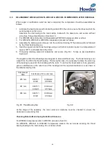
When repair or rectification work has been completed, the compressor should be assembled as
follows:
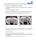
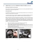
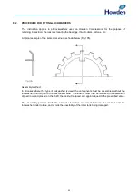
1. Lubricate the bearing bores with lubricating oil and lift in the rotors, ensure the lobes mesh at the
serial numbers on the rotors.
Assemble the inlet casing to the main casing, locate with the dowel pins, and secure with set
pins. (See Torque Specification in Section 9.1)
2. For WRV204 Refer to Section 8.2 Re-assembly WRV163 Compressor after overhaul.
3. For WRVi255, WRVi321 & WRVi365 compressors proceed as follows:
4. Assemble the balance piston sleeves into the outlet end casing, fit the balance pistons followed
by the thrust bearing sleeves.
5. Heat the angular contact thrust bearings using an oil bath or induction heater to a temperature of
approx 100°C, and assemble to the rotors.
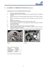
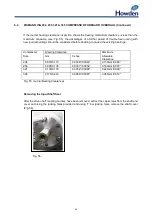
6. Fit bearing retaining plate and lockwasher and secure (Fig. 63). Torque as per specification
Section 9.1
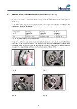
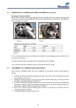
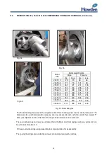
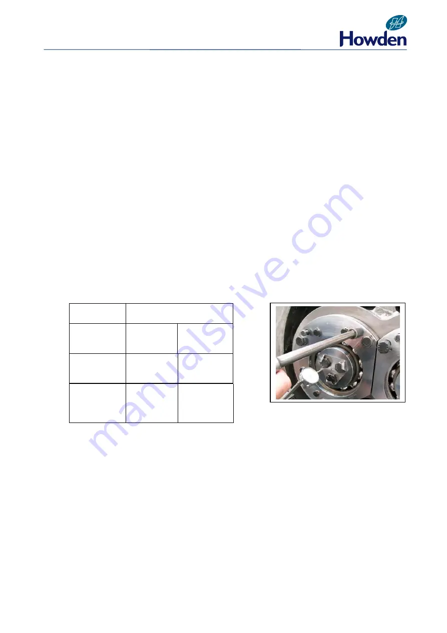
The angular contact thrust bearings are designed to take axial thrust only. The thrust bearing is not
a tight fit on the OD in the thrust housing. This being the case, it is necessary to clamp the outer ring
of the bearing to prevent it from rotating with the rotor. To do this the thrust plate is to be ground to
give an interference on the outer race of the bearings and the required interference is as shown in
the table below (Fig. 68).
Compressor
Size
Interference fit in outer race
255 mm
0.0015”/
0.004”
0.038mm/
0.100mm
321 mm
0.0015”/
0.00
45”
0.040mm/
0.115mm
365 mm
0.0015”/
0.004”
0.038mm/
0.100mm
Fig. 68 Thrust Bearing Nip
Fig. 69
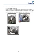
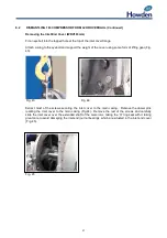
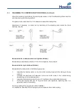
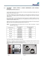
At this stage of the assembly, the rotor outlet end clearance must be checked to ensure the
clearance is correct (Fig. 69).
Checking Rotor to Main Casing Outlet End Clearance
For WRV204 Compressors refer to WRV163 procedure Sect 8.3
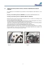
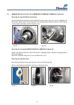
For WRVi255, WRVi321 & WRVi365 Compressors slacken the set screws securing the thrust
bearing housing to the main casing. Do not remove them.
Содержание WRV
Страница 1: ...WRV WRVi COMPRESSOR RANGE SERVICE MANUAL...
Страница 3: ...2 SECTION 1 FOREWORD...
Страница 5: ...4 HOWDEN SECTION 2 DESCRIPTION...
Страница 10: ...9 SECTION 3 INSTALLATION...
Страница 14: ...13 SECTION 4 FIRST START UP...
Страница 16: ...15 SECTION 5 NORMAL OPERATION...
Страница 18: ...17 SECTION 6 PROCEDURES DURING SHUTDOWN...
Страница 20: ...19 SECTION 7 MAINTENANCE...
Страница 33: ...32 SECTION 8 OVERHAUL...
Страница 50: ...49 SECTION 9 SPECIAL INSTRUCTIONS...
Страница 57: ...56 SECTION 10 SPARES...
Страница 64: ...63 Printed in the UK Issue HCL September 2012 Howden Compressors Limited...

