29
7.4
CHECKING CLEARANCES (Continued)
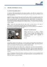
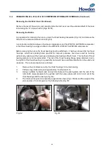
To check the Thrust Bearing Float
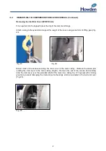
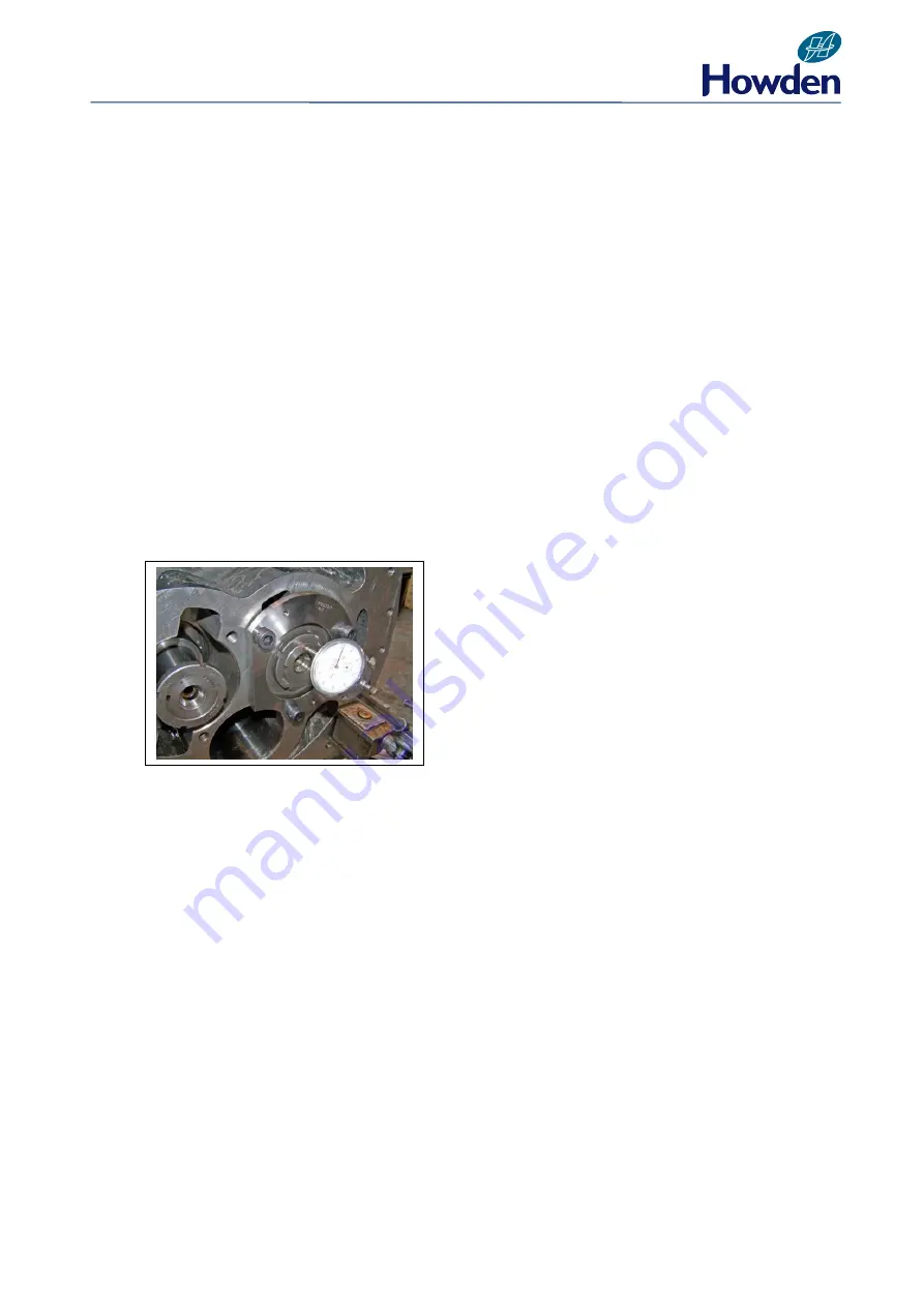
To check the thrust bearing float, set a dial indicator up axially on the shaft end. Access must be
gained to the inlet end of the female rotor by removing the rotor cover. Push or pull the rotor, to its
limit in either direction.
Record the indicator reading and then push or pull the rotor to its limit in the opposite direction. The
difference in indicator readings is the thrust bearing axial float. This procedure must be followed for
both male and female rotors. This reading should not exceed 0.025
mm (0.001”). Any increase over
this reading will necessitate replacement of the thrust bearings. The thrust bearings are fitted with a
small pre-load, the maximum float permitted is 0.025
mm (0.001”). If in excess of this the bearings
must be changed.
NOTE:
Should the thrust bearing float be within limits, no further work on the rotors is
recommended, i.e. journal bearing clearances would not necessarily be measured.
Any increase on this figure will necessitate replacement of the thrust bearings, the procedure for
which is described per Section 8.2-8.3 or 8.4-8.5.
NOTES:
It is extremely important that the fasteners on the thrust bearing retaining plates of the WRV163 and
WRV204 compressors are torqued exactly to the specified setting of 14Nm. Over-torquing will not
permit correct operation of the thrust bearing, resulting in premature failure.
Should the thrust bearing float be within limits, no further work on the rotors is recommended, ie,
journal bearing clearances would not necessarily be measured. Where the thrust bearing float is
outside limits and, therefore, the thrust bearings have to be slackened off and removed, the
opportunity would then be taken to measure journal bearing condition, and proceed as for major
overhaul.
Where a compressor is fitted with condition monitoring, no check on the thrust bearings will be
required. See Section 7.1. A 4 yearly check on the guide block wear, and an annual check on the
PTFE seal condition is all that is necessary.
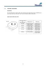
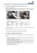
Maximum Thrust Bearing Float
Please note that due to a change in bearing
selection, which now means that bearings are fitted
with a pre-load condition, the maximum float
permitted is 0.025mm
(0.001”) regardless of
compressor size.
Fig. 23
Содержание WRV
Страница 1: ...WRV WRVi COMPRESSOR RANGE SERVICE MANUAL...
Страница 3: ...2 SECTION 1 FOREWORD...
Страница 5: ...4 HOWDEN SECTION 2 DESCRIPTION...
Страница 10: ...9 SECTION 3 INSTALLATION...
Страница 14: ...13 SECTION 4 FIRST START UP...
Страница 16: ...15 SECTION 5 NORMAL OPERATION...
Страница 18: ...17 SECTION 6 PROCEDURES DURING SHUTDOWN...
Страница 20: ...19 SECTION 7 MAINTENANCE...
Страница 33: ...32 SECTION 8 OVERHAUL...
Страница 50: ...49 SECTION 9 SPECIAL INSTRUCTIONS...
Страница 57: ...56 SECTION 10 SPARES...
Страница 64: ...63 Printed in the UK Issue HCL September 2012 Howden Compressors Limited...

