


10
3.1
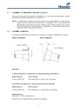
ALIGNMENT OF COMPRESSOR COUPLINGS
The couplings supplied with this compressor must be aligned using the method described below:
If a compressor only is supplied the coupling alignment tolerance figures can be seen under Section
3.2.
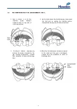
During alignment checks, both half couplings should be rotated together from 0° to 90°, 180°, 270°
and 360° and readings of radial and facial alignment recorded. Turning both half couplings together
ensures that readings are recorded at the same point on each half coupling, thus eliminating the
effect of any irregularities on the outside diameters, or faces of the half coupling.
Commence alignment by setting the faces of the coupling halves parallel in the vertical plane. The
axes will now be parallel in the horizontal plane and further adjustment to obtain the correct centre
heights will require equal shimming under each foot of the unit being adjusted. The units are now
positioned vertically and horizontally.
Further adjustment to obtain the correct coupling gap, radial and facial alignment, will only require
movement of one unit on the existing shim size.
Coupling gap dimensions should be set with the couplings held in a repeatable position, ie, hard
together or hard apart. This ensures that each coupling half is removed to the same axial position as
each check is made.
The actual coupling gap should be correct when the shafts are in their normal running condition. If
the combined float of the driving and driven shaft exceeds the coupling gap tolerance, the value and
direction of float for both shafts will be shown on the General Arrangement Drawing.
When setting the gap the axial float of eac
h shaft should be determined and the “hard together” or
“hard apart” dimension calculated.
Example:
Compressor driven directly by a turbine.
Compressor shaft float
0.050mm (0.002”)
Turbine shaft float
0.250mm (0.010”)
The normal running position of the compressor shaft is towards the turbine and the turbine normally
runs thrusting towards the compressor.
Required gap
3.175mm (0.125”)
If the gap is checked with the couplings “hard apart” it should be:
Plus Compressor shaft float
0.000mm (0.000”)
Plus Turbine shaft float
0.250mm (0.010”)
= “Hard apart” gap
3.425mm (0.135”)
Содержание WRV
Страница 1: ...WRV WRVi COMPRESSOR RANGE SERVICE MANUAL...
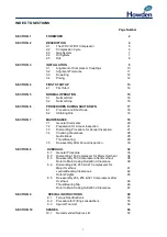
Страница 3: ...2 SECTION 1 FOREWORD...
Страница 5: ...4 HOWDEN SECTION 2 DESCRIPTION...
Страница 10: ...9 SECTION 3 INSTALLATION...
Страница 14: ...13 SECTION 4 FIRST START UP...
Страница 16: ...15 SECTION 5 NORMAL OPERATION...
Страница 18: ...17 SECTION 6 PROCEDURES DURING SHUTDOWN...
Страница 20: ...19 SECTION 7 MAINTENANCE...
Страница 33: ...32 SECTION 8 OVERHAUL...
Страница 50: ...49 SECTION 9 SPECIAL INSTRUCTIONS...
Страница 57: ...56 SECTION 10 SPARES...
Страница 64: ...63 Printed in the UK Issue HCL September 2012 Howden Compressors Limited...