background image

30

Chapter 6

Configuration / Setting

Subject to technical changes
Rev. 1.01.08

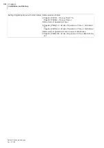
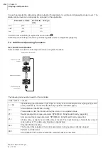
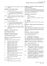
[P020]t4 - Process Timer 4

Value range: [0]...9999 seconds

Ø

[P017]t1 - Process Timer 1

[P021]AmAn - Automatic Manual Mode

[P022]tC.AL - Autom. Short Circuit Supervision of
Sensor

[P023]tC.ti - Testing Period for 

Manual Short Circuit

Supervision of Sensor

Value range: [0]...999 seconds

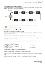
Is the temperature increase after the expiration of the
testing period not 5K

,

 although the controller outputs

the maximum degree of operation

,

 a short circuit alarm

was detected.

The zone is deactivated (degree of operation 0%). In
the actual value display tCSC is shown. The zone can
be activated by the acknowledgement of the alarm.

[P024]APPL - Application

Without function.

6.2

Control parameter

This parameter group consists of the control parame--
ters and the parameters that affect the automatic con--
trol parameter calculation.

[P025]H.Pb - Proportional Band of 

Heating

Value range: 0.0...25.5% [6.5]

[P026]H.td - Derivative Time of 

Heating

Value range: 0...2000 seconds [50]

[P027]H.ti - Integral Time of 

Heating

Value range: 0...2000 seconds [50]

[P028]H.Ct - Sampling Time of 

Heating

Value range: 0.2...90.0 seconds [0.2]

[P029]C.Pb - Proportional Band of 

Cooling

Value range: 0.0...25.5% [6.5]

[P030]C.td - Derivative Time of 

Cooling

Value range: 0...2000 seconds [50]

[P031]C.ti - Integral Time of 

Cooling

Value range: 0...2000 seconds [50]

[P032]C.Ct - Sampling Time of 

Cooling

Value range: 0.2...90.0 seconds [1.0]

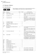
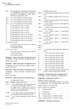
[P033]IdE.H - Identification Heating

on

Is an invalid measured value (due to sensor
break) detected during control mode

,

 the con--

troller switches automatically over to manual
mode.  The last averaged degree of operation
determined by the controller is used as the
new degree of operation.

[oFF]

Function deactivated

on

The function supervises the status and the wi-r-
ing of the sensor of short circuit.

The function is calculated by means of the ac-
tual value

,

 the degree of operation and a

Ó

[P028]

H

.Ct - Sampling Time of 

H

eating

(page 30) dependent time. This assures the
detection of already existing as well as sud-
denly arising short circuits. 

A short circuit alarm of a sensor is displayed

,

 if

Ú

after a sampling time dependent time no
temperature rising is detected although the
controller outputs the maximum degree of
operation.

Ú

a sudden drop of temperature is detected.

After detection of a short circuit of the sensor
tCSC is shown in the actual value display and
the zone is deactivated. The zone can be ac-ti-
vated by the acknowledgement of the alarms
(

Ó

Information Level (page 20)).

[oFF]

Function deactivated

[on]

The control parameters 

Heating

 are calcula-t-

ed after the first change of the set point grea-ter
than 50K after...

Ú

a reset of a zone (

Ó

[P006]ZonE - Status of

Zone (page 28) = off)

Ú

or switch-on of controller

Ú

or after setpoint value 0°C/32K

are calculated during heating-up. 

During the identification phase Id and actual
value are shown alternately in the display.

oFF

Function deactivated

No parameter calculation for control parame--
ters of heating is done during the heating up
phase. The heating is done due to the adju-st-
ed set point.

Содержание hotcontrol C248

Страница 1: ...Operating Instructions hotcontrol C248 hotcontrol C296 Single Loop Temperature Controller Rev 1 00 08 05 2017 Translation of original operating instructions ...

Страница 2: ......
Страница 3: ...n terminal 1 and 16 Ú Connect the heater with power supply and Solid State Relay Use ultra rapid micro fuse or ultra rapid auto matic circuit breaker for fuse protection of the heating circuit Ú Connect the power supply of the controller by terminal 13 and 14 e g 230 VAC Notice necessarily the specification of the power supply of the controller 85 250 VAC or 24 V Provide fuse protection Step 2 Adj...

Страница 4: ...Option B 14 Analog Outputs Option A and B 14 Digital in outputs Option A and B 15 5 Display and Operation 17 Front view 17 Display Loc 17 Display of Examples of Operation 18 Display of Buttons 18 Display of LED 18 Steps of Operation in Flow Chart 18 Operation Levels 19 Direct data entry of set point and degree of operation 20 Information Level 20 User Level 22 System Level 22 Two Methods of Data E...

Страница 5: ...n of Alarm Flags 37 Definition of Timers 38 Configuration of Operation 39 Configuration of Data Interface 40 Basic settings for Special Applications 40 Application Hot Runner Control 40 Application Extrusion 41 Application Hot Air 41 Alarm Hysteresis Function 41 7 Appendix 42 Parameters factory delivery status 42 Firmware update 45 Version History 48 ...

Страница 6: ...ons are available on request Symbols and explanation 2 Warranty Conditions This product is subject to the legal warranty time periods for faults or deficiencies in manufacture Content of Warranty If a malfunction relatively occurs through the manufacture Hotset GmbH repairs or replaces the nonconforming product according to their own discretion The following repairs do not fall under the warranty ...

Страница 7: ...minals must be dimensioned for the corresponding amperage Furthermore all connec tions are to be carried out according to the valid VDE Specification and or the respective national specifications Ensure in particular that the AC power supply is not connected with the logic output or the low voltage in put Overload protection For the power supply of the controller and the controller outputs use a f...

Страница 8: ...m the type plate The controller is packed in a robust cardboard box Check the packaging and then the temperature controller for identifiable damage incurred during transit If damage is identified then please get in touch with the transportation company In case of damage DO NOT put the controller into operation Two securing brackets see figure and the operating instructions are in cluded in the box...

Страница 9: ...ptical coupler Relay Digital output 4 TS R Optical coupler Relay Option A RS 485 U I DIO RS485 T Not existing Serial interface 2 wire Analog output 0 2 10VDC Analog output 0 4 20mA Digital inputs outputs Serial interface 4 wire RS 485 U I DIO RS485 T Not existing Serial interface 2 wire Analog output 0 2 10VDC Analog output 0 4 20mA Digital inputs outputs Serial interface 4 wire Option B CAN U I D...

Страница 10: ...ut has to be prepared according to the following sketch When fitting more than one controller in a control panel the correct spacing of the controllers is necessary A spac ing of 10mm in horizontal and 38mm in vertical direction is recommended C248 C296 45 mm 0 5 0 0 45 mm 0 5 0 0 55mm 83mm 92mm 0 5 0 0 45 mm 0 5 0 0 55mm 130mm ...

Страница 11: ...nting system The housing can be mount ed removed without any tools To mount the controller remove the securing brackets Press the securing brackets at the end 1 move it backward 2 out of the guides Pass the controller into the front side of the control panel cut out or re move it from the front side Refit the securing brackets into the guides again and push it forward ...

Страница 12: ...tion An incorrect configuration can lead to damage to the control section or to injuries to persons C248 C296 With power supply 85 250 VAC With power supply 24 V With power supply 85 250 VAC With power supply 24 V 1 2 3 4 5 6 7 8 9 10 11 12 13 14 15 16 N L 0V 12VDC DOUT 1 DOUT 2 DIN GND STI I R TS DIN1 DOUT1 RS485 TX AOUT1 RS485 TX 4 wire DIN1 DOUT1 RS485 TX AOUT1 RS485 TX 4 wire DIN2 DOUT2 CAN L ...

Страница 13: ... 5W 6 5W Fuse 200mA time lag 800mA time lag 200mA time lag 800mA time lag C248 C296 Define measuring input A Ú Page35 P072 SEn Sensor Type of Measuring Input A Ú Page37 P075 oFF A Offset of Measuring Input A Define measuring input B and C only C296 Ú Page37 P078 Aib L Lower Display Limit of Measuring Input B Ú Page37 P079 Aib H Upper Display Limit of Measuring Input B Ú Page37 P080 AiC L Lower Dis...

Страница 14: ...eating Ú Page33 P050 rEL C Relay Output Cooling Is control output used for output of alarm Ú Page37 P082 A1 d1 Alarm Flag 1 Definition 1 to Page38 P089 A4 d2 Alarm Flag 4 Definition 2 Additional setting if output is used for output of temperature limit alarms Define alarm limits Ú Page28 P007 Li 1 Temperature Limit 1 to Page28 P010 Li 4 Temperature Limit 4 Define mode of operation of alarm limits ...

Страница 15: ...f operation of timer in case of disturbance Ú Page39 P098 t rES Mode of Operation of Timer after Soft Re set C248 C296 Define measuring method Ú Page33 P053 Cur d Current Supervision Function Define upper limit of measurement range Ú Page33 P054 Cur E Final Value of Measurement Range of Current Supervision Define heating current and tolerance Ú Set point of current either directly entered Page28 P...

Страница 16: ...ine as rS Ú Page35 P065 OPt b Definition of Option B define as rS Define communication protocol Ú Page40 P102 S Pro Protocol of Serial Interface Define setting of interface Ú Page40 P101 S Adr Address of serial interface Ú Page40 P103 S bd Baud Rate of Serial Interface Ú Page40 P104 S Sto Stop Bits of Serial Interface Ú Page40 P105 S PAr Parity of Serial Interface Additional setting if communicati...

Страница 17: ...ay Output Heating Ú Page33 P050 rEL C Relay Output Cooling Is control output used for output of alarm Ú Page37 P082 A1 d1 Alarm Flag 1 Definition 1 to Page38 P089 A4 d2 Alarm Flag 4 Definition 2 Additional setting if output is used for output of temperature limit alarms Define alarm limits Ú Page28 P007 Li 1 Temperature Limit 1 to Page28 P010 Li 4 Temperature Limit 4 Define mode of operation of al...

Страница 18: ...imer Ú Page29 P017 t1 Process Timer 1 to Page30 P020 t4 Process Timer 4 Define mode of operation of timer Ú Page38 P090 t1 d1 Mode of Operation of Timer 1 Definition 1 to Page39 P097 t4 d2 Mode of Operation of Timer 4 Definition 2 Define mode of operation of timer in case of disturbance Ú Page39 P098 t rES Mode of Operation of Timer after Soft Re set ...

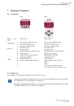
Страница 19: ...Decrease button Increase button Parameter button Edit Enter button LEDs A B C D E F G H Output heating Output cooling alarm output 3 Digital input activated Temperature unit F Communication RS485 CAN Bus Digital input 1 activated Digital output 2 activated Temperature unit F Output heating Output cooling alarm output 3 Alarm 1 Alarm 2 Communication RS485 CAN Bus see Ó P087 A3 d2 Alarm Flag 3 Defin...

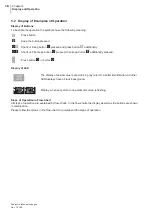
Страница 20: ...the buttons are shown in combination Please follow the arrows in the flow chart to comprehend the steps of operation a Press button a Keep the button pressed df Shortcut Keep button d pressed and press button f additionally df Shortcut First keep button d pressed then keep button f additionally pressed Press button s or button d The display of actual value set point is in gray color for a better i...

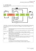
Страница 21: ...t and actual value and degree of operation respec tively are displayed Information Level Display and operation of the often used process parameters set point manual mode heating current alarm Is Loc displayed in the actual value display see chapter ÓDisplay Loc page 17 User Level USEr Display and operation of parameters that are occasionally displayed and changed The list of parameters can be arra...

Страница 22: ...data entry is canceled The program returns to main level and displays actual value set point and actual value degree of operation re spec tively Is Loc displayed in the actual value display see chapter ÓDisplay Loc page 17 5 3 2 Information Level In the information level set point manual mode heating current and alarms are directly accessible by button a At information level Ú set points for tempe...

Страница 23: ...value Confirm change a Select Heating current Select manual mode Deactivate man ual mode Display actual value set point Activating man ual mode Enable entry of degree of operation Change degree of oper ation Confirm change a Select alarm display Enable current transfer No current transfer Display cur rent setpoint value Change current setpoint value Execute current transfer Activate current transf...

Страница 24: ...value set point display Is Loc displayed in the actual value display see chapter ÓDisplay Loc page 17 Select user level Exit user level Display for about 1 second Scroll backwards Scroll forwards Display actual value set point Ú By call of system level SYS is shortly shown in the LED display Ú In the system level it is feasible to scroll forward and backward between the parameters The system level...

Страница 25: ...consecutively in between 0 5 seconds Select user level Display Actual value set point Display for about 1 second Select user level Setpoint value flashes Setpoint value flashes Display for about 1 sec ond Change setpoint value directly Change of setpoint value Confirm change and call the next parameter Confirm change and call the next parameter Direct Data Entry Edit on The set point can be entere...

Страница 26: ...Change code number Activate function by code number Code number Function 1 100 Input blocking see parameter Ó P110 ULoc Entry Lock on User System level page 40 is tem porary released 1 minute after the last key operation activated again 111 Start automatic identification cooling Prerequisite to start the function is that the zone is in a adjusted status 211 Deactivate input block see parameter Ó P...

Страница 27: ...matically blocked Unblocking is done by entry of as code number see chapter ÓEnter Code Number page 24 Input blocking is automatically reactivated 1 minute after the last key operation The setting of parameter Ó P110 ULoc Entry Lock on User System level page 40 0 deactivates the input block The setting of parameter Ó P110 ULoc Entry Lock on User System level page 40 is fail safe Press button for a...

Страница 28: ...ing x mAnU Manual mode x AL Measuring range exceeded tempera ture alarm x Control heating unit and power control ler e g SSR Control if the sensor related with the heating unit is connected with the con troller SSr Current alarm heating off x Control power controller e g SSR Control if the current transformer relat ed to the heating unit is connected with the controller tCSC Sensor alarm x Control...

Страница 29: ...HotsetGmbH 27 Operating instructions hotcontrol C248 296 Subject to technical changes Rev 1 01 08 HoFF Actuator deactivated x Display Meaning Alarm Status Fault Correction ...

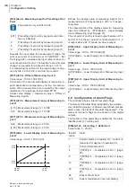
Страница 30: ... Temperature Limit 1 page 32 to Ó P044 Li 4d Definition of Temperature Limit 4 page 32 the function of the limit value is deter mined Ó P044 Li 4d Definition of Temperature Limit 4 page 32 P008 Li 2 Temperature Limit 2 Value range 999 0 1500 0 5 Ø P007 Li 1 Temperature Limit 1 P009 Li 3 Temperature Limit 3 Value range 999 0 1500 0 0 Ø P007 Li 1 Temperature Limit 1 P010 Li 4 Temperature Limit 4 Val...

Страница 31: ...e 0 9999 seconds Ø P017 t1 Process Timer 1 P019 t3 Process Timer 3 Value range 0 9999 seconds Ø P017 t1 Process Timer 1 0 Temperature ramp deactivated 0 Temperature ramp at set point increase acti vated 0 Temperature ramp at set point increase and decrease activated 50 60 70 80 90 100 110 120 SP C oFF Automatic ramp deactivated on Consistent heating of several controllers Prerequisites Ú Controlle...

Страница 32: ...cation Heating on Is an invalid measured value due to sensor break detected during control mode the con troller switches automatically over to manual mode The last averaged degree of operation determined by the controller is used as the new degree of operation oFF Function deactivated on The function supervises the status and the wi r ing of the sensor of short circuit The function is calculated b...

Страница 33: ...t point the calculation of the control parameters of cool ing is started 5 After the calculation of the control parameters of cooling is completed the controller operates with the adjusted set point P037 C Con Control Parameter Cooling constant after Identification Heating In accordance with the dimensioning of the efficiency of heating and of cooling at zones the control parameters Cooling can ge...

Страница 34: ...Upper limitation of degree of operation in control mode P046 Out C Maximum Degree of Operation of Cooling Value range 100 0 Lower limitation of degree of operation in control mode P047 Out m Maximum Degree of Operation in Manual Mode Value range 100 100 Upper limitation of degree of operation in Ó P002 mAnU Manual Mode page 28 Function also active with Ó P022 tC AL Autom Short Circuit Supervision ...

Страница 35: ...Ú sampling time is set to minimum 10 sec onds oFF output of degree of operation with quickly clocked short pulses e g output for Solid State Relays If degree of operation 0 on Ú only one on off switching operation at control output during one sampling cycle Ú sampling time is set to minimum 10 sec onds oFF output of degree of operation with quickly clocked short pulses e g output for Solid State R...

Страница 36: ...ree of operation changes are output Not at P066 P067 Co CL Close valve For valve control Only degree of operation changes are output Not at P066 P067 Is digital input 1 active oFF Digital input without function P on it is indicated to the controller that the pow er controller for heating is connected Is digital input 1 inactive the control is stopped no control signal and no current tol eran ce al...

Страница 37: ...Type of Measuring Input A P073 SEn C Measuring Input for Control Parameter is only valid for C296 Presetting which of the three actual values or a combination of these are used for control For measuring input B and C the limit ranges config ured by AIb L Aib H AiC L und AiC H are valid oFF Option B not available CAn CAN Bus dI Digital input dO Digital output AO Analog output 0 10VDC 0 20mA AO O An...

Страница 38: ...imal value is output P079 Aib H Upper Display Limit of Measuring In put B Value range 100 0 1500 0 999 9 Ø P078 Aib L Lower Display Limit of Measuring Input B P080 AiC L Lower Display Limit of Measuring In put C Value range 100 0 1500 0 0 0 Ø P078 Aib L Lower Display Limit of Measuring Input B P081 AiC H Upper Display Limit of Measuring In put C Value range 100 0 1500 0 999 9 Ø P078 Aib L Lower Di...

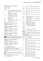
Страница 39: ...e effect like controller start Identifi cation Alarm 1 Error during identification phase drift 2 Actual value greater than end of measure ment range 4 Hysteresis Limit Value Li3 Li4 ØAlarm Hysteresis Function 8 Hysteresis Limit Value Li1 Li2 ØAlarm Hysteresis Function 16 Without function 32 Without function 64 Alarm flag can be acknowledged 128 Alarm flag storing oFF No function P on The power con...

Страница 40: ... reaches the 5K band around the set point directly after start of the controller After termination Start of timer 4 L t1 Timer is started when the actual value reaches the 5K band around the set point After termination Start of timer 1 L t2 Timer is started when the actual value reaches the 5K band around the set point After termination Start of timer 2 L t3 Timer is started when the actual value ...

Страница 41: ...up Function After start the controller operates for a definite time with the set point for start up Ó P013 SP 4 Set Point 4 page 29 is used for this function Ú Define mode of operation for the start up timer after start of the controller Ó P090 t1 d1 Mode of Operation of Timer 1 Defini tion 1 page 38 SP4 A and Ó P091 t1 d2 Mode of Operation of Timer 1 Definition 2 page 38 AL t2 Ú Define period of ...

Страница 42: ... Pb Proportional Band of Heating page 30 15 Ó P026 H td Derivative Time of Heating page 30 1 Ó P027 H ti Integral Time of Heating page 30 3 Ó P028 H Ct Sampling Time of Heating page 30 0 3 In case these control parameters are not leading to an optimal result for your hot air zones please con tact Hotset GmbH For a further adaptation of the heating control param eters please watch the actual value ...

Страница 43: ...Edit Ó P026 H td Derivative Time of Heating 0 2000 50 Edit Ó P027 H ti Integral Time of Heating 0 2000 50 Edit Ó P028 H Ct Sampling Time of Heating 0 2 90 0 0 2 Edit Ó P029 C Pb Proportional Band of Cooling 0 0 25 5 6 5 Edit Ó P030 C td Derivative Time of Cooling 0 2000 50 Edit Ó P031 C ti Integral Time of Cooling 0 2000 50 Edit Ó P032 C Ct Sampling Time of Cooling 0 2 90 0 1 0 Edit Ó P033 IdE H I...

Страница 44: ... on C oFF C on SP bA SP br AL CL t1 t2 t3 t4 t1 t2 t3 t4 iLoc oFF hidE Ó P069 dIn b Mode of Operation of Digital Input Option B oFF P on P oFF SP2 A SP3 A SP4 A SP2 r SP3 r SP4 r H oFF H on C oFF C on SP bA SP br AL CL t1 t2 t3 t4 t1 t2 t3 t4 iLoc oFF hidE Ó P070 AO A Mode of Operation of Analog Out put Option A oFF out H out C SEn C IntF S C b S C C oFF hidE Ó P071 AO b Mode of Operation of Analo...

Страница 45: ... hidE Ó P093 t2 d2 Mode of Operation of Timer 2 Def inition 2 oFF Auto A t1 A t2 A t3 A t4 t1 t2 t3 t4 AL t1 AL t2 AL t3 AL t4 L t1 L t2 L t3 L t4 AL L AS AS t1 AS t2 AS t3 AS t4 oFF hidE Ó P094 t3 d1 Mode of Operation of Timer 3 Def inition 1 oFF P on P oFF SP2 A SP3 A SP4 A SP2 r SP3 r SP4 r H oFF H on C oFF C on oFF hidE Ó P095 t3 d2 Mode of Operation of Timer 3 Def inition 2 oFF Auto A t1 A t2...

Страница 46: ...t be identical with the address of the controller with which the firmware update should be car ried out Click with right hand mouse button on the controller in the left window Select the firmware update menu item in the context menu In the update dialog window the HEX file of the update firmware must first be se lected For this purpose click on the button File and select the corresponding HEX file...

Страница 47: ...ovide a non damaged HEX file Start firmware update through clicking on the button Start A progress column displays the current status of the update procedure The up date process lasts about 4 minutes with deactivated verify function and with acti vated verify function about 7 minutes After successful firmware update the con troller is restarted The dialog box can be closed ...

Страница 48: ...de Ú Parameter number added P Ú Alarm hysteresis function added P041 P044 P083 P085 P087 P089 1 01 03 05 20 2009 In detail the following amendments were made Ú OptionA B RS485 4 wire added Ú Parameter OPt A interface RS485 named rS Ú Resulting address CAN corrected Ú Example of application hot runner control added 1 01 02 05 08 2008 Functional extension S C b and S C C for parameter AO A AO b Spec...

Отзывы: