36
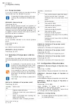
Chapter 6
Configuration / Setting
Subject to technical changes
Rev. 1.01.08
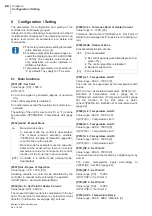
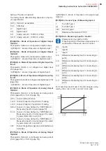
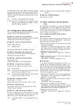
[P074]Sen.S - Measuring Input for Presetting of Set
Point
Parameter is only valid for C296.
Exceeds the input value the measurement range
,
the
current set point of control is set to
Ó
[P001]SP - Set
Point (page 28)
,
otherwise the input value is taken for
current set point of control. The function "set point value
change" is executed for a set point change > 0.5 °C.
For measuring input B and C the input ranges confi-g-
ured by Aib.L
,
Aib.
H,
AiC.L und AiC.
H
are valid.
[P075]oFF.A - Offset of
Measuring Input A
Value range: -100.0...100.0 [0.0]
Correction of the actual value display of measuring in-
put A dependent on temperature unit. E.g. for compen-
sation of the measurement error caused by the output
resistance of a resistance thermometer Pt100.
Actual value display = measured value + ’Offset of
Measuring Input A’
[P076]oFF.b - Measurement range of
Measuring In-
put B
[P077]oFF.C - Measurement range of
Measuring In-
put C
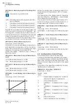
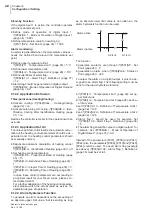
[P078]Aib.L - Lower Display Limit of
Measuring In-
put B
Value range: -100.0...1500.0 [0.0]
Defines the display value of measuring input B for a
measured value of 0 respectively 2 VDC or 0 respec--
tively 4mA.
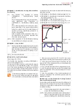
The characteristic of the display values for measuring
input B is defined by
Ó
[P079]Aib.
H
- Upper Display
Limit of Measuring Input B (page 37).
The set point of control is linear output between AI*.L
and AI*.
H
. For the set point of control beneath AI*.L
,
0
is output; above AI*.
H,
maximal value is output.
[P079]Aib.H - Upper Display Limit of
Measuring In-
put B
Value range: -100.0...1500.0 [999.9]
Ø
[P078]Aib.L - Lower Display Limit of Measuring Input
B
[P080]AiC.L - Lower Display Limit of
Measuring In-
put C
Value range: -100.0...1500.0 [0.0]
Ø
[P078]Aib.L - Lower Display Limit of Measuring Input
B
[P081]AiC.H - Upper Display Limit of
Measuring In-
put C
Value range: -100.0...1500.0 [999.9]
Ø
[P078]Aib.L - Lower Display Limit of Measuring Input
B
6.8
Configuration of Alarm Flags
The controller offers a total of four alarm flags.
The status of the alarm flags is defined by two parame--
ters (definition groups). Is at least one defined process
alarm active
,
the status of the alarm flag equals 1. The
status of the alarm flags can be shown on the digital
outputs.
The function of the alarm flag is defined by the alarm
identifiers set (0 = nothing set).
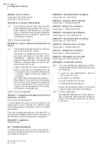
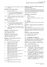
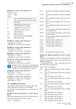
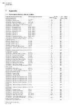
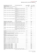
[P082]A1.d1 - Alarm Flag 1, Definition 1
Value range: 0...255 [4]
[oFF]
Presetting of set point by keypad
,
serial inter--
face or CAN-Bus.
A
Presetting of set point by measuring input A.
b
Presetting of set point by measuring input B.
C
Presetting of set point by measuring input C.
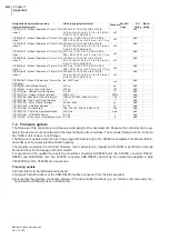
[0-10] Measurement range 0...10 VDC
2-10
Measurement range 2...10 VDC
0-20
Measurement range 0...20 mA
[4-20] Measurement range 4...20 mA
0/2 VDC
0/4 mA
10 VDC
20 mA
AIb.L
AIC.L
AIb.h
AIC.h
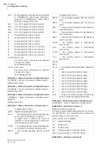
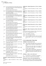
Identifi-
cation
Alarm
1
Current alarm on heating off - current is
measured for degree of operation 0%
2
Current tolerance alarm
4
Ó
[P007]Li.1 - Temperature Limit 1 (page
28)
8
Ó
[P008]Li.2 - Temperature Limit 2 (page
28)
16
Ó
[P009]Li.3 - Temperature Limit 3 (page
28)
32
Ó
[P010]Li.4 - Temperature Limit 4 (page
28)
64
Sensor short-circuit
128
Sensor break/sensor incorrect polarity
Содержание hotcontrol C248
Страница 2: ......

