40
Section 15: Rudder, Elevator and Throttle Pushrod
Installation
Required Parts
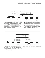
• Control horn (2)
• Fuselage
• Wire keeper (2)
• Clevis (2)
• Easy connector
• Clevis keeper (2)
• 19
1
⁄
2
" pushrod wire, 1.5mm
• 30" pushrod wire, 2-56 threaded on one end (2)
Required Tools and Adhesives
• Felt-tipped pen/pencil
• Hobby knife
• Needle-nose/Z-bend pliers
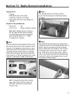
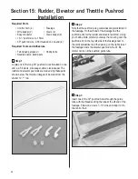
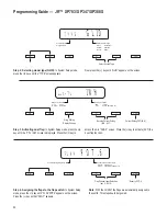
Step 1
Locate one of the long 30" pushrod wires threaded on one
end, a 2-56 clevis, wire keeper, and a clevis keeper. The
rudder and elevator pushrods are made using these parts
shown below. The throttle linkage will be made from the
shorter 19
1
⁄
2
" rod.
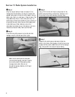
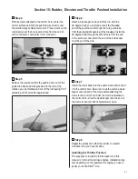
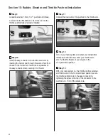
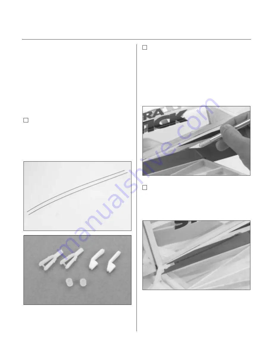
Step 2
Note that the pushrod wire guide tubes are preinstalled in
the fuselage. On the aft end of the fuselage find the
pushrod exits for the rudder and elevator pushrod. Using
your hobby knife, carefully cut away the covering over the
pushrod exit on the top left side of the fuselage next to
the vertical stabilizer and the opening on the right side of
the fuselage where the elevator pushrod will exit. Be
careful not to cut the pushrod guide tube.
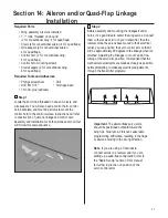
Step 3
Insert one of the 30" pushrod wires through the guide
tube with the threads exiting the tube at the aft end of the
fuselage. Screw on a clevis 7–10 turns and snap it onto
the control horn.


