69-0774B—1
4
T874D MULTISTAGE THERMOSTAT AND Q674A,D SUBBASES
M5632A
1.2 .8 .6
.3
.2
1.5
.4
50 60 70 80
HEAT
HEATING SET
POINT LEVER
50 60 70 80
COOL
COOLING SET
POINT LEVER
1.2
.8
.6
.3
.2
1.5
.4
.12
1.2
.4
.6
.3
.2
.15
.12
.1
0
.8
1.2
.4
.6
.3
.2
.15
.12
.8
.5
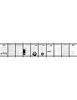
MOVE INDICATOR TO
MATCH CURRENT RATING
OF PRIMARY CONTROL
STAGE ONE
ANTICIPATOR
HEATING
CONTROL
STAGE TWO
ANTICIPATOR
HEATING CONTROL
M5069
Fig. 8. Adjustable heat anticipator scales.
The current draw of each heating stage must be measured
with the thermostat removed and the power on to the
heating system.
1.
Connect an ac ammeter of appropriate range
between the heating terminals of the subbase:
Stage 1: between W1 and RH.
Stage 2: between W2 and RH.
2.
After one minute, read the ammeter and record the
reading.
Stage 1: __________ amperes.
Stage 2: __________ amperes.
3.
After mounting the thermostat, set the adjustable
heat anticipator to match the readings measured in
step 3.
NOTE:
If equipment cycles too fast, set the indicator to a
higher current rating, not more than one-half
division at a time, and recheck the cycle rate.
Most conventional two-stage heating equipment
is designed to operate at three cycles per hour
per stage and one-stage heating equipment at
six cycles per hour, at 50 percent load condition.
Temperature Setting
Move the heating and cooling setpoint levers to the
desired comfort positions. See Fig. 9. One lever control all
stages of heating, and the other lever controls all stages of
cooling. The minimum differential between the heating and
the cooling setpoint is 3
°
F (1.7
°
C), which means the
setting levers are made so they cannot be set closer
together than 3
°
F (1.7
°
C).
Fig. 9. Location of external components.
Subbase Setting
System switching positions control the system operation
as follows:
HEAT—heating system is automatically controlled by
the thermostat. Cooling system is off.
AUTO—thermostat automatically changes between
heat and cool modes, depending on indoor tempera-
ture.
COOL—cooling system is automatically controlled by
the thermosat. Heating system is off.
Fan switching positions control fan operation as follows:
ON—fan operates continuosly.
AUTO—fan operatres as controlled by the thermostat in
heat pump systems or conventional cooling mode;
fan operates as controlled by the plenum switch in
conventional heating mode.
To move subbase switches to the desired control posi-
tions, use thumb and index finger to slide the lever. The
lever must stop over desired function indicator position for
proper circuit operation.
CHECKOUT
Heating
Move the system switch on the Q674 Subbase to HEAT.
Move the setpoint lever on the T874 Thermostat about
10
°
F (6
°
C) above room temperature. Both stages of
heating and fan should start. Move the setpoint lever about
10
°
F (6
°
C) below room temperature. Heating and fan
should shut off.
NOTE:
To prevent compressor short cycling, some
manufacturer’s equipment includes a minimum
off timer to provide a 5-minute time delay before
turning the compressor on after the thermostat
last turned the compressor off, or after the
system first received power. This delay protects
the compressor.
Cooling
CAUTION
If outside air or heat exchange medium (water) is
below 50
°
F (10
°
C), do not operate cooling.
Move the system switch on the Q674 Subbase to COOL.
Move the setpoint lever on the T874 Thermostat about
10
°
F (6
°
C) below room temperature. Cooling and fan
should start (see NOTE above). Move the setpoint lever
about 10
°
F (6
°
C) above room temperature. Cooling and
fan should stop.
NOTE:
If using a Control Module Mark IV, there are time
delays built in. Check your Mark IV instructions
for details.
Fan
Move the fan switch to the ON position, the fan should run
continuously. When the fan switch is in the AUTO position,
fan operation is controlled by the heating or cooling
system.