


7810iR Internet Communication Module Installation and Setup Guide
5-6
685 Automation Mode
When configured for 685 Automation Mode, subscriber alarm messages received on the
10BaseT connection are routed directly to Automation equipment. Using an RS232 serial
interface, the 7810iR communicates with Automation equipment in the same way as a 685
Digital Alarm Receiver.
New alarms are briefly displayed in the 7810iR New Alarm window with no audible alert.
When the Automation equipment receives and acknowledges the alarm message, the 7810iR
automatically moves the current message into the Alarm History window. The next alarm in
the New Alarm buffer will be displayed in the New Alarm window.
If the Fail to Manual option is selected during the 7810iR programming, the 7810iR will
revert to Manual Mode when communication with the Automation system is lost. When
communication is restored, the 7810iR will send up to 100 unreported messages to the
automation equipment.
Both the New Alarm window and the Alarm History window are first-in, first-out (FIFO)
buffers that are limited to 100 entries. Once 100 messages have been received in the Alarm
History buffer, the next message received will push the oldest alarm off the list. There is no
method to save or archive messages in these buffers.
If the Fail to Manual option is not selected, a loss of communications between the 7810iR and
Automation will block the AlarmNet connection. This makes all incoming messages from
AlarmNet undeliverable or bounced. In this condition, AlarmNet will deliver all subscribers
message traffic to the Backup CS immediately.
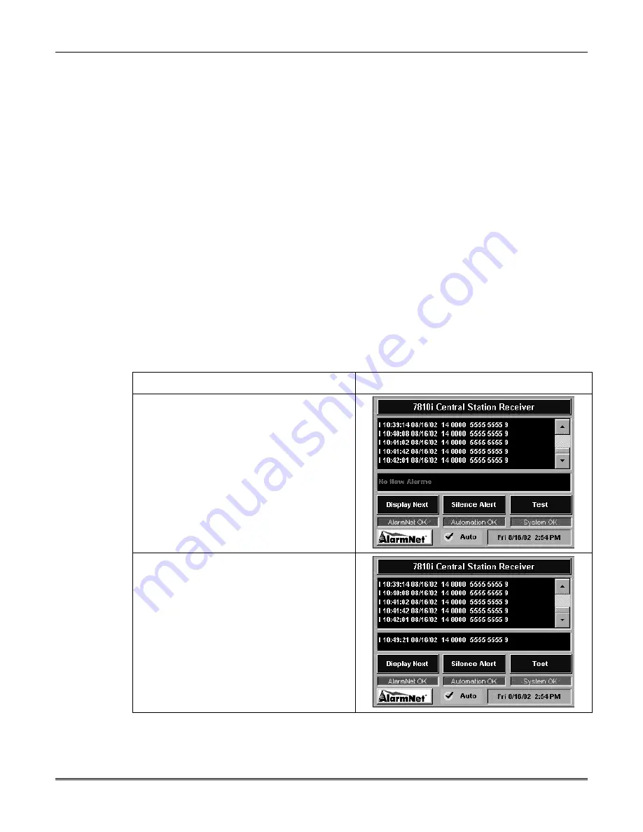
Alarm Sequence in 685 Automation Mode
Action Screen
Display
1. 685 Automation “Home” screen.
2. New alarm received.
Содержание AlarmNet 7810iR
Страница 2: ......
Страница 6: ...7810iR Internet Communication Module Installation and Setup Guide 1 2 ...
Страница 12: ...7810iR Internet Communication Module Installation and Setup Guide 2 6 ...
Страница 16: ...7810iR Internet Communication Module Installation and Setup Guide 3 4 ...
Страница 62: ...7810iR Internet Communication Module Installation and Setup Guide 7 10 ...