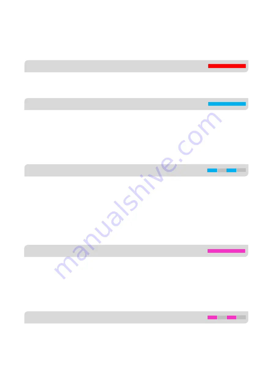
HOBBYEAGLE A3 SUPER 3 Скачать руководство пользователя страница 14

[email protected]                                                                                                                                      14 

GYRO-OFF MODE


Solid Red


NORMAL MODE


Solid Blue


TRAINER MODE


Solid Violet


AUTO-LEVEL MODE


Flashing Violet


ATTI-LOCK MODE


Flashing Blue


5.


FLIGHT MODE


A3S3  provides  6  different  flight  modes  which  can  be  changed  by  a  3-position  switch  (or  6-position  logic  switch)  of  the 

transmitter during flight. 


Gyro-Off mode is usually used for testing purpose only. When this mode is selected, the gyro will be deactivated completely. 

The plane will be completely under the control of your transmitter as it was before installing the gyro.


The Normal mode (also referred to as Rate mode) is the most basic function of the gyro. It works based on the rotation rate 

control  of  each  axis  of  the  plane.  When  operating  in  this  mode,  the  gyro  will  only  correct  currently  occurring  rotational 

movements,  a  momentary  reaction  will  be  applied  to  the  servos  when  the  plane  rotating  on  corresponding  axis,  after 

rotation the servos will move back to their neutral position as soon as the plane standing still immediately. Normal mode can 

be used with nearly any size and type of airplanes. It can effectively improve the stability and precision of the plane and 

reduce the stall point specially.   


The Atti-Lock mode is also referred to as the 3D mode or AVCS mode. Different from normal mode, the gyro will perform a 

permanent correction for rotational movements on each axis constantly. Moving the sticks will make the plane rotating at a 

certain speed on the corresponding axis, as long as the sticks are released the plane will stop and lock its current position 

immediately. This operation mode is well suited for practicing basic 3D maneuvers such as hovering or knife edge, so we 

also call it 3D flight mode. Since it can help you to lock the attitude of the plane, it’s also helpful for landing. It is worth noting 

that when the gyro is operated in this mode, the servos will keep driving to one side if a specific control input is given, and 

the servos will not center even if the sticks are released, this is normal.   


In Trainer mode you can only tilt the plane to a certain angle by giving aileron or elevator stick input. Roll and loop are not 

allowed in this mode, the plane will be stabilized all the time, independent of any stick input. This prevents the plane from 

being tilted into a larger angle that may cause a danger. As soon as the sticks are released, the plane will be brought back 

to horizontal position automatically. You can use this mode as emergency rescue, or in other applications, e.g. to have a 

training for new beginners or to use for FPV. The maximum angle allowed of trainer mode can be set using the program 

card or the software. In addition, changing the stick rate can also affect the max tilt angle.   


When operating in Auto-Level mode, the plane will be brought to normal horizontal position automatically when releasing 

the  sticks.  Different  from  the  Trainer  mode,  there  is  no  maximum  angle  limitation  in  this  mode  and  the  plane  will  be 

stabilized only when there is no specific control inputs from aileron and elevator sticks. This mode can be used if the pilot 

becomes disoriented and would like to save the plane from crashing.   


Содержание A3 SUPER 3

Страница 1: ...support hobbyeagle com 1 A3 SUPER 3 INSTRUCTION MANUAL For Firmware Version 1 0 Data Version 1 0 Oct 25 2017 Revision...

Страница 2: ...15 7 Gain Settings 17 8 LED Descriptions 18 9 Config Software 18 9 1 Install the USB Driver 19 9 2 Overview of the Software 20 9 3 Flight Mode 21 9 4 Wing Type 21 9 5 Mount Orientation 22 9 6 Gyro Set...

Страница 3: ...vos including the settings of Sub Trim and Trimming buttons ALWAYS fine tune the surfaces by using the Servo Trimming function P25 provided by A3S3 itself Because the trimming changes from the transmi...

Страница 4: ...ition flight mode switching supported 4 Compatible with most standard receivers standard PPM single line receivers and Futaba s S Bus and S Bus 2 receivers 5 7 wing types dual aileron dual elevator de...

Страница 5: ...plane still and wait for the gyro to initialize The initialization will take about 2 seconds and the LED will blink blue several times Don t move the plane and keep all sticks in their original posit...

Страница 6: ...tion In the same way a hover calibration is recommended to perform if the Auto Hover mode will be used in the future See Page 29 9 9 2 Hover Calibration 10 TEST FLIGHT Up to now you have basically fin...

Страница 7: ...down socket pointing to rear 1 You need only one piece of the tapes each time a soft or thick mounting may probably impact the performance of the gyro 2 Never use the hot melt glue or nylon ties to fi...

Страница 8: ...channels If the wing type currently selected contains only one aileron or elevator servo A2 or E2 will become a pass through channel automatically it means that the input signal applied to A2 or E2 wi...

Страница 9: ...the servo connected at OUT5 in this case if E2 is disconnected OUT2 and OUT5 will be switched to be controlled by E simultaneously 4 Most flying wings have no rudder in this case R is unnecessary to...

Страница 10: ...r receiver then connect the ESC or throttle servo to OUT4 and the gear servo to OUT5 The wing type currently selected determines when the pass through function of A2 and E2 will come into effect In th...

Страница 11: ...kets 3 Please refer to the instructions of your transmitter for setting up the 3 position switch for flight mode control and the knob or slider for remote master gain control 4 You have to restart the...

Страница 12: ...channel assignment to recognize the channels from receiver The default assignment is CH1 Aileron CH2 Elevator CH3 Throttle CH4 Rudder CH5 Flight Mode CH6 Aileron 2 CH7 Elevator 2 CH8 Master Gain You...

Страница 13: ...support hobbyeagle com 13 Programming the channel assignment in the software...

Страница 14: ...s long as the sticks are released the plane will stop and lock its current position immediately This operation mode is well suited for practicing basic 3D maneuvers such as hovering or knife edge so w...

Страница 15: ...ht mode associated to each position can be preset in the software or program card 5 2 6 POSITION MODE SWITCHING A3S3 also supports 6 position flight mode switching which allows you switch among all 6...

Страница 16: ...kly move the right wing downward around the roll axis the right aileron surface should flap down and the left flap up as shown below Quickly move the nose of the plane downward around the pitch axis t...

Страница 17: ...control command sent from the transmitter during flight However if the gain is too large the plane will become too sensitive and overshoot A fine lock gain should be able to lock the attitude of the...

Страница 18: ...lashing Power on initialization and self test Solid Red Gyro Off Mode Solid Blue Normal Mode Blue Flashing Atti Lock Mode Solid Violet Trainer Mode Violet Flashing Auto Level Mode Violet Fast Flashing...

Страница 19: ...on Laboratories CP210x VCP driver as shown below After setup insert the USB adapter into the PC and wait until the windows finishes scanning and installing the new hardware Then open the Device Manage...

Страница 20: ...The icon means that the port has been opened successfully If you get a greyed icon like you will need to verify that you have inserted the USB adapter and installed the USB driver successfully 3 Syste...

Страница 21: ...ition of the switch blue background color is used to indicate the position currently selected when you flipping the switch 3 Max Tilt Angle The max tilt angle setting is only used for Trainer mode Adj...

Страница 22: ...3S3 The orientation in the picture should look as same as yours 9 6 GYRO SETTINGS 1 Gyro On Off You can disable the gyro separately for each channel 2 Gyro Direction Reverse the gyro if it reacts in o...

Страница 23: ...down list then adjust the rate and expo settings after you have finished the adjustment click Write to save the settings to the gyro The rate is used to adjust the amount of throw of the sticks it can...

Страница 24: ...left travel limit center position and right travel limit from left to right 2 Sub Trim The sub trim function is used to adjust the servo neutral position and to make fine adjustment to the control sur...

Страница 25: ...the first one selected after you entering the procedure When the desired servo has been chosen move and hold the aileron stick into one direction to change the center position for it when it reaches...

Страница 26: ...cedure When the desired servo has been chosen move and hold the aileron stick into one direction to move the servo until it reaches the maximum allowed throw without any binding or stall then release...

Страница 27: ...e real time angle on roll and pitch axes 4 Level and Hover Offset Auto Calibration You can modify the level and hover offset values here the value can be adjusted from 25 degree to 25 degree with the...

Страница 28: ...has to be performed once after installation Before calibrating the plane should be placed on the horizontal ground and make the wing parallel to the ground Make the plane slightly nose up because a c...

Страница 29: ...he procedure is quite similar to that of level calibration The only difference is in the first step Before calibrating you need to lift the plane and make it vertical to the ground instead of putting...

Страница 30: ...chanical characteristics changes of the sensor The calibration should be done on a horizontal desktop follow the steps below until all of the 6 different orientations have been completed successfully...

Страница 31: ...cker showing down press Next to continue and wait until the calibration is done just like the last step Now stand it up with the arrow pointing to the table Fix it with your fingers and make sure it i...

Страница 32: ...nue and wait until the calibration is done Now change to another orientation and make the gyro look like it is in the picture with the long side of the housing on the table and the DATA socket up Fix...

Страница 33: ...gyro around and make the DATA socket down Again fix it with your fingers and press Next to continue and wait until the calibration is done After you have finished all of the steps above you can see th...

Страница 34: ...fault is DLPF_42Hz lower the frequency can get a better reduction of noise from external vibrations 4 Gyro Software Filter Set the cut off frequency of the software low pass filter for the gyro The de...

Страница 35: ...the current settings will be overwritten 10 3 LANGUAGE SELECTION The program supports Chinese and English languages You can select the language in the system menu Press and hold the ENT button while...

Страница 36: ...dder from 0 to 100 06 Gyro Setup 01 Gyro On Off Enable or disable the gyro for aileron elevator and rudder 02 Gyro Reverse Reverse the gyro direction for aileron elevator and rudder 03 Max Tilt Angle...

Страница 37: ...libration Perform an auto hover calibration 11 Advanced Setting 01 Stick Deadband Adjustment range 0 20 the default is 5 02 Stick Filter Set the cut off frequency of the low pass filter for the stick...

Страница 38: ...4g PWM 920uS 2120uS with 1520uS center length 50 333Hz Input Voltage 4 8V 8 4V Operating Temperature 10 50 Size 43 27 14mm Weight 10g excluding wires VOLTAGE PROTECTOR It s recommended to use the supp...

Отзывы: