background image


50 


C13UE001-1903 


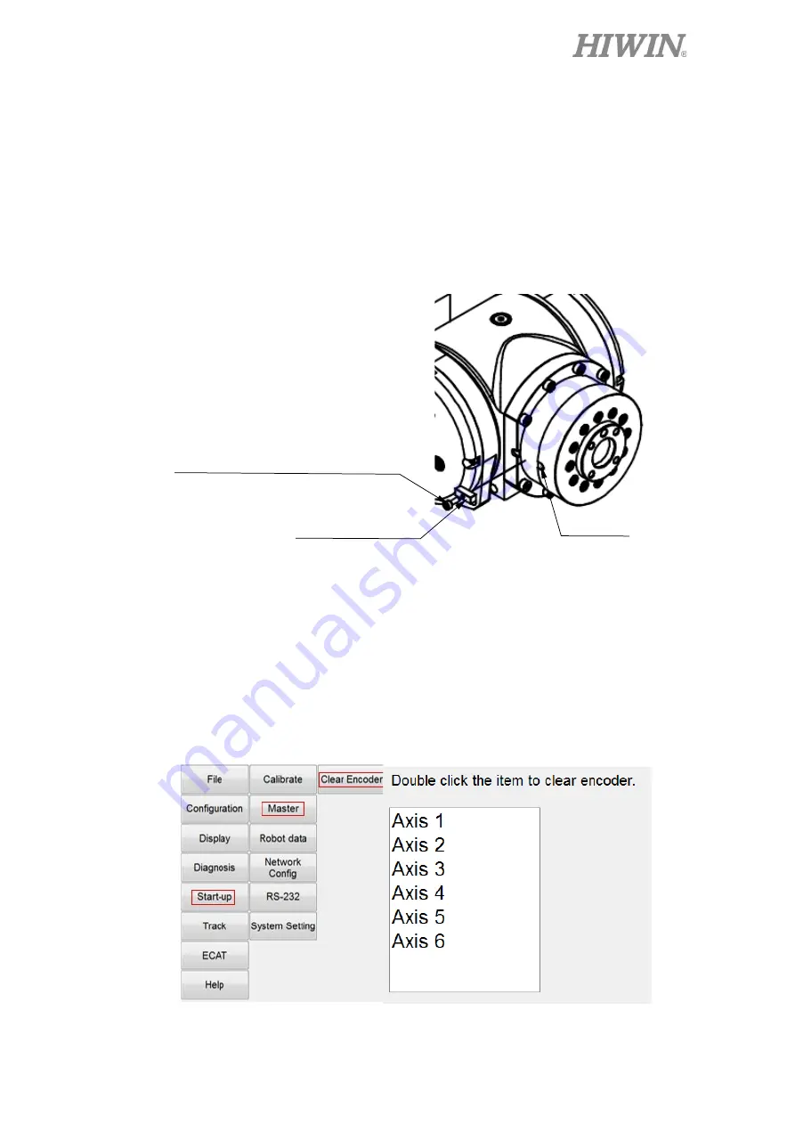
J6-axis Zero-position setting 

Step1.


Operate J6 at low speed to align the calibration mark with the keyway. 

Step2.


Insert the calibration tool(B) to the keyway to calibrate Zero-position. (The 
hexagon socket screw can be secured to the calibration tool(B) in advance.) 

Step3.


Finish calibration and remove the calibration tool(B) by using the hexagon 
socket screw. 

Step4.


Clear encoder by HRSS. (Refer to page 53) 

Step5.


Zero-position setting of J6 axis is completed.                                                                                                                                                                        


Figure 4-7 Illustration of J6-axis Zero- position setting 


Clear encoder by HRSS 

Step1.


Select the “JOINT” as the coordinate system. 

Step2.


Move the robot to the Zero-position. (Refer to section 4-1) 

Step3.


Click Main Menu>>Start-up>>Master>>Clear Encoder. (As shown in 
Figure 4-8) 

Step4.


Double click the axis to clear encoder. (As shown in Figure 4-8) 


Figure 4-8 Clear encoder by HRSS 

Calibration tool(B)


Keyway


Hexagon socket head cap screw


M3

×

0.5P

×

8L(Nylok) 


Содержание RA610-GB Series

Страница 1: ...www hiwin tw User Manual Articulated Robot RA610 GB RT610 GB Original Instruction...

Страница 2: ...cal Ball Type HG EG WE MG CG Quiet Type QH QE QW QR Other RG E2 PG SE RC Bearing Machine tools Robot Crossed Roller Bearings Ballscrew Bearings Linear Bearing Support Unit DATORKER Robot Reducer Robot...

Страница 3: ...y the unauthorized staff Installing non genuine HIWIN products The following conditions are not covered by the warranty Product serial number or date of manufacture month and year cannot be verified U...

Страница 4: ...this user manual Symbol Description Failure to follow instructions with this symbol may result in serious hazard or personal injury Please be sure to comply with these instructions Failure to follow i...

Страница 5: ...ollows Operator Turns robot controller ON OFF Starts robot program from operator s panel Restore system alarm status Programmer or teaching operator Operates the robot Teaches robot inside the safety...

Страница 6: ...y fence while operating the robot A safety zone should be established around the robot with an appropriate safety device to stop the unauthorized personnel from access While installing or removing mec...

Страница 7: ...op button must be pressed 3 3 Maintenance Please contact us if the procedure not specified by HIWIN is needed Please contact us if the replacement of the component not specified by HIWIN is needed Be...

Страница 8: ...5 Pneumatic Hydraulic System When using the pneumatic or hydraulic system the gripped workpiece may fall due to insufficient pressure or gravity The pneumatic system must be equipped with the relief...

Страница 9: ...ronment for more detailed information please see section 1 5 environmental conditions Use is not permitted under the following conditions Use in potentially explosive environments Use without performi...

Страница 10: ...ON RANGE 30 4 5 WRIST LOAD CONDITIONS 34 3 EQUIPMENT MOUNTING SURFACE AND INTERFACE 38 3 1 MOUNTING SURFACE FOR END EFFECTOR 38 3 2 MOUNTING SURFACE ON THE ROBOT 38 3 3 INTERFACE OF AIR SUPPLY 41 3 4...

Страница 11: ...ate Robot type Remark 1 0 0 2018 05 25 RA610 GB RT610 GB First edition released 1 0 1 2019 01 03 RA610 GB RT610 GB Added new chapter 5 manual brake release device 1 0 2 2019 02 19 RA610 GB RT610 GB Mo...

Страница 12: ...robot to the desired position by forklift truck Step4 Remove the suspension plate and firmly secure the robot Transport by sling and crane Step1 Move the robot into its transport position and the angl...

Страница 13: ...5 45 J6 0 0 0 0 Before carrying the robot be sure to remove the end effector which changes the center of gravity Please keep stable slow down and avoid excessive vibration or shock during transportati...

Страница 14: ...a RA610 1355 GB Transport dimensions RT610 1355 GB Transport dimensions Figure 1 2 b RA610 1476 GB Transport dimensions RT610 1476 GB Transport dimensions Center of gravity Center of gravity Center o...

Страница 15: ...c RA610 1672 GB Transport dimensions RT610 1672 GB Transport dimensions Figure 1 2 d RA610 1869 GB Transport dimensions RT610 1869 GB Transport dimensions Center of gravity Center of gravity Center o...

Страница 16: ...1355 GB Transport by forklift truck Figure 1 3 b RA610 1476 GB Transport by forklift truck RT610 1476 GB Transport by forklift truck Suspension plate Screw 4 M8x1 25Px20L Washer 4 M8 Direction for for...

Страница 17: ...1672 GB Transport by forklift truck Figure 1 3 d RA610 1869 GB Transport by forklift truck RT610 1869 GB Transport by forklift truck Suspension plate Screw 4 M8x1 25Px20L Washer 4 M8 Direction for for...

Страница 18: ...3UE001 1903 Figure 1 4 a RA610 1355 GB Transport by sling RT610 1355 GB Transport by sling Figure 1 4 b RA610 1476 GB Transport by sling RT610 1476 GB Transport by sling Center of gravity Center of gr...

Страница 19: ...3UE001 1903 Figure 1 4 c RA610 1672 GB Transport by sling RT610 1672 GB Transport by sling Figure 1 4 d RA610 1869 GB Transport by sling RT610 1869 GB Transport by sling Center of gravity Center of gr...

Страница 20: ...18 C13UE001 1903 Figure 1 4 e Eye bolt securement Sling installation position 2 M12 Eyebolt...

Страница 21: ...how the forces and moments acting on the installation surface The installation surface must have sufficient strength to withstand the dynamic movement of the robot when operating at maximum speed The...

Страница 22: ...7 Power cuts Stop 12129 6903 6985 5433 Ensure the installation surface is smooth plane which is recommended to be 6 3a or less for the roughness If the installation surface is rough the robot could pr...

Страница 23: ...and the pin assignment of the power supply and signal connector are shown in Figure 1 9 and Table 1 2 The connection of RA610 GB and RT610 GB are the same The following figures only show the connectio...

Страница 24: ...ble 1 2 Pin 0assignment of CN2 connector Code RA610 GB RT610 GB A Air out socket Air in out socket B Air in socket Air in out socket C Battery box Battery box D Power signal socket Power signal socket...

Страница 25: ...in Table 1 3 Table 1 3 Ambient conditions Ambient conditions Ambient temperature 0 45 Note 1 Ambient relative humidity 75 R H or less No condensation permissible Altitude Up to 1000 m above mean sea l...

Страница 26: ...Table 1 4 Standard and optional equipment list Item HIWIN Part No Standard Optional Remark Robot accessory kit 4C201HU3 Contains suspension plate set calibration tool set and end effector I O connecto...

Страница 27: ...25 C13UE001 1903 2 Basic Specifications 2 1 Description of Model Name There is a model name on the specification label of RA610 GB and RT610 GB The explanation of model name is shown below...

Страница 28: ...prevent colliding to operator during operation Grounding Make sure grounding is completed or it will cause electric shock Read manual Read user manual before operating manipulator Electric shock Pay m...

Страница 29: ...air tube for air input of RA610 GB Air out The connection port of air tube for air output of RA610 GB Air in out The connection port of air tube for air input and output of RT610 GB Grease in The hole...

Страница 30: ...y 0 05 mm 0 06mm Motion range J1 170 170 J2 95 150 J3 185 85 J4 190 190 J5 135 135 J6 360 360 Maximum speed J1 192 s 3 35rad s J2 206 s 3 59rad s J3 219 s 3 82rad s J4 450 s 7 85rad s J5 450 s 7 85rad...

Страница 31: ...load capacity please refer to section 2 5 Note 3 The cycle time is the time that the RA610 1476 GB is loaded at 10kg to forward and backward move in the vertical height 25mm and the horizontal distanc...

Страница 32: ...03 2 4 Outer Dimensions and Motion Range The outer dimensions and motion range are shown in Figure 2 3 a d Figure 2 3 a RA610 1355 GB Outer dimension and motion range RT610 1355 GB Outer dimension and...

Страница 33: ...31 C13UE001 1903 Figure 2 3 b RA610 1476 GB Outer dimension and motion range RT610 1476 GB Outer dimension and motion range...

Страница 34: ...32 C13UE001 1903 Figure 2 3 c RA610 1672 GB Outer dimension and motion range RT610 1672 GB Outer dimension and motion range...

Страница 35: ...33 C13UE001 1903 Figure 2 3 d RA610 1869 GB Outer dimension and motion range RT610 1869 GB Outer dimension and motion range...

Страница 36: ...only limited by the weight of the load but also limited by the position of load s center of gravity Figure 2 4 a d shows the allowable position of load s center of gravity when the robot is loaded Fi...

Страница 37: ...35 C13UE001 1903 Figure 2 4 b RA610 1476 GB Wrist moment diagram RT610 1476 GB Wrist moment diagram...

Страница 38: ...36 C13UE001 1903 Figure 2 4 c RA610 1672 GB Wrist moment diagram RT610 1672 GB Wrist moment diagram...

Страница 39: ...37 C13UE001 1903 Figure 2 4 d RA610 1869 GB Wrist moment diagram RT610 1869 GB Wrist moment diagram...

Страница 40: ...3 1 Mounting surface for end effector 3 2 Mounting Surface on the Robot Mounting surfaces for the peripheral equipment are shown in Figure 3 2 a e The mounting surfaces of RA610 GB and RT610 GB are t...

Страница 41: ...robot RT610 1355 GB Mounting surfaces on the robot Figure 3 2 c RA610 1476 GB Mounting surfaces on the robot RT610 1476 GB Mounting surfaces on the robot J1 rotation center J5 rotation center J3 rota...

Страница 42: ...igure 3 2 e RA610 1869 GB Mounting surfaces on the robot RT610 1869 GB Mounting surfaces on the robot When other equipment is installed on the robot be aware of the interference between robot and moto...

Страница 43: ...f the air tube in the robot is 4mm The secure holes for the nozzle are M5 0 8P 8DP The schematic diagram of pneumatic circuit is shown in Figure 3 3 b Figure 3 3 a The interface for air supply of RA61...

Страница 44: ...AIR OUT of RT610 GB are installed on the rear of J1 as shown in Figure 3 4 and the outer diameter of the air tube in the robot is 4mm The secure holes for the nozzle are M5 0 8P 8DP Figure 3 4 The int...

Страница 45: ...he wiring diagram of R I O interface The connection of two wire proximity switch used on customer side is shown in Figure 3 11 The R I O interfaces of RA610 GB and RT610 GB are the same The following...

Страница 46: ...44 C13UE001 1903 Figure 3 7 Wiring diagram of input Standard Sinking type Figure 3 8 Wiring diagram of input Optional Sourcing type...

Страница 47: ...45 C13UE001 1903 Figure 3 9 Wiring diagram of output Standard Sinking type Figure 3 10 Wiring diagram of output Optional Sourcing type...

Страница 48: ...t at each pin is 100mA The two wire proximity switch might have residual voltage which can cause robot input error So it is suggested to choose a proper resistance and connect it by parallel connectio...

Страница 49: ...ation tools is shown in Figure 4 2 to Figure 4 7 below Calibration tool A Calibration tool B Figure 4 1 The calibration tool set J1 axis Zero position setting Step1 Operate J1 at low speed to align th...

Страница 50: ...of J2 axis is completed Figure 4 3 Illustration of J2 axis Zero position setting J3 axis Zero position setting Step1 Operate J3 at low speed to align the pinhole of J4 with the pinhole of J3 Step2 In...

Страница 51: ...53 Step5 Zero position setting of J4 axis is completed Figure 4 5 Illustration of J4 axis Zero position setting J5 axis Zero position setting Step1 Operate J5 at low speed to align the pinhole of J6...

Страница 52: ...gon socket screw Step4 Clear encoder by HRSS Refer to page 53 Step5 Zero position setting of J6 axis is completed Figure 4 7 Illustration of J6 axis Zero position setting Clear encoder by HRSS Step1 S...

Страница 53: ...uted by trained staff When the manual brake release device is executed J4 axis must be securely fixed by a crane to prevent an unexpected drop of J2 axis and J3 axis Please carefully read the section...

Страница 54: ...appearance 3 Please make sure the voltage of power source and the voltage requirement of the device are the same before connecting this device to the power Connecting wrong voltage to the device will...

Страница 55: ...53 C13UE001 1903 Corresponding manipulator model name 1 RA605 XXX GB RT605 XXX GB 2 RA610 XXXX GB RT610 XXXX GB...

Страница 56: ...54 C13UE001 1903 5 3 Operation Name descriptions of the manual brake release device and their functions...

Страница 57: ...note that the axes of the switch are not in sequence due to the gravity comes from releasing particular axis brake Thus J2 and J3 are bound together to prevent the unexpected falling when releasing t...

Страница 58: ...aily Inspection Items Inspection item Remedy Before turning power ON 1 any of the robot installation screws cover installation screws and end effector installation screws loose Securely tighten the sc...

Страница 59: ...hanged for a long period Please change the grease Refer to section 6 2 3 8 If the bearing or the reducer has been damaged by the rolling surface or the gear tooth surface Please contact HIWIN directly...

Страница 60: ...stem of the controller Inspection item C 6 months 1920 hours 1 Check whether the timing belt is normal Adjust the tension of the timing belt If the friction at the timing belt is severe replace it Ref...

Страница 61: ...59 C13UE001 1903 Table 6 3 Inspection schedule...

Страница 62: ...batteries of the robot is shown in Figure 6 1 and described as below Step1 Press the emergency stop button to prohibit the movement of the robot motion Step2 Ensure the robot and controller are connec...

Страница 63: ...excessively worn wearing about half of the tooth width the belt tooth is cracked or the belt is broken replace the belt but you are required to re origin the points to correct the points Belt Tension...

Страница 64: ...Removing the cover Before replacing the belt remove the cover of J5 and J6 The M3x0 5Px8L screws are used as shown in Figure 6 3 Figure 6 3 Removing the cover Axis Belt type Width mm Span mm Tension...

Страница 65: ...aragraph to adjust the belt tension Adjust J5 axis timing belt Step1 Loose the two fixing screws on motor flange so that the motor can be moved No need to remove the screws Step2 Refer to Table 6 4 lo...

Страница 66: ...agraph to adjust the belt tension Adjust J6 axis timing belt Step1 Loosen the two fixing screws on motor flange so that the motor can be moved No need to remove the screws Step2 Refer to Table 6 4 loo...

Страница 67: ...r needs to be removed for J5 grease replenishment Part Grease nipple Lubrication grease Quantity Lubricatio n interval J1 reduction gear M6 VIGOGREASE REO 700 ml 3Year 11520Hr J2 reduction gear M6 VIG...

Страница 68: ...e inlet and install the grease nipple Step3 Remove the screw of the air vent Step4 Replenish the grease from the grease inlet by the grease gun Step5 Refer to Table 6 5 for the amount of grease Step6...

Страница 69: ...sell or export products or processes restricted under the Foreign Trade Act or related regulations Export of restricted products should be approved by proper authorities in accordance with relevant la...

Страница 70: ...n ch HIWIN s r o BRNO CZECH REPUBLIC www hiwin cz info hiwin cz HIWIN SINGAPORE SINGAPORE www hiwin sg info hiwin sg HIWIN KOREA SUWON MASAN KOREA www hiwin kr info hiwin kr HIWIN CHINA SUZHOU CHINA w...

Отзывы: