ModBus Data Listing
Appendix B
B–28
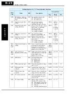
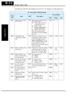
A056
DC braking / edge or
level detection for [DB]
input
R/W Two options; select codes:
00... Edge detection
01... Level detection
0061h
0, 1
—
A061
Frequency upper limit
setting
R/W Sets a limit on output
frequency less than the
maximum frequency (A004).
Range is from frequency lower
limit (A062) to maximum
frequency (A004).
0.0.. setting is disabled
>0.1 setting is enabled
0062h
(A062 x
10) to
(A004 x
10),
0=disable
>1=enabl
e
0.1 Hz
A261
Frequency upper limit
setting, 2nd motor
R/W
0063h
A062
Frequency lower limit
setting
R/W Sets a limit on output
frequency greater than zero.
Range is start frequency
(B082) to frequency upper
limit (A061).
0.0.. setting is disabled
>0.1 setting is enabled
0064h
(B082 x
10) to
(A061 x
10),
0=disable
>1=enabl
e
0.1 Hz
A262
Frequency lower limit
setting, 2nd motor
R/W
0065h
A063,
A065,
A067
Jump (center) frequency
setting
R/W Up to 3 output frequencies can
be defined for the output to
jump past to avoid motor
resonances (center frequency)
Range is 0.0 to 400.0 Hz
0066h,
0068h
006Ah
0 to 4000
0.1 Hz
A064,
A066,
A068
Jump (hysteresis)
frequency width setting
R/W Defines the distance from the
center frequency at which the
jump around occurs
Range is 0.0 to 10.0 Hz
0067h
0069h
006Bh
0 to 100
0.1 Hz
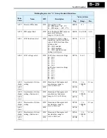
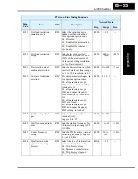
A071
PID Enable
R/W Enables PID function,
two option codes:
00... PID Disable
01... PID Enable
006Ch
0, 1
—
A072
PID proportional gain
R/W Proportional gain has a range
of 0.2 to 5.0
006Dh
2 to 50
0.1
A073
PID integral time
constant
R/W Integral time constant has a
range of 0.0 to 150 seconds
006Eh
0 to 1500
0.1 sec
A074
PID derivative time
constant
R/W Derivative time constant has a
range of 0.0 to 100 seconds
006Fh
0 to 1000
0.1 sec
A075
PV scale conversion
R/W Process Variable (PV) scale
factor (multiplier), range of
0.01 to 99.99
0070h
1 to 9999
0.01
A076
PV source setting
R/W Selects source of Process
Variable (PV), option codes:
00... [OI] terminal (current in)
01... [O] terminal (voltage in)
02... Network
03... Calculate function output
0071h
0, 1, 2, 3
—
Holding Registers for “A” Group Standard Functions
Func.
Code
Name
R/W
Description
Network Data
Reg.
Range
Res.
Содержание SJ200 Series
Страница 53: ...SJ200 Inverter Inverter Mounting and Installation 2 15 Dimensional drawings continued SJ200 007HFEF 007HFU ...
Страница 185: ...Inverter System Accessories In This Chapter page Introduction 2 Component Descriptions 3 Dynamic Braking 5 5 ...
Страница 207: ...Glossary and Bibliography In This Appendix page Glossary 2 Bibliography 8 A ...
Страница 254: ...Drive Parameter Settings Tables In This Appendix page Introduction 2 Parameter Settings for Keypad Entry 2 C ...
Страница 265: ...CE EMC Installation Guidelines In This Appendix page CE EMC Installation Guidelines 2 Hitachi EMC Recommendations 6 D ...
Страница 269: ...SJ200 Inverter Appendix D D 5 L1 L2 L3 PE SJ200 inverter with book type filter M 3 ...

