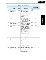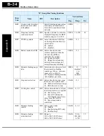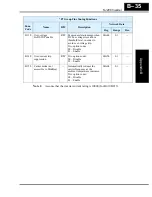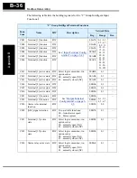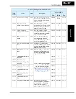
ModBus Data Listing
Appendix B
B–22
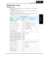
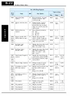
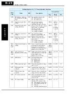
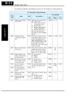
D001
Output frequency
monitor
R
Real-time display of output
frequency to motor, from
0.0 to 400.0 Hz
00Ah
0 to
4000
0.1 Hz
D002
Output current monitor
*1
R
Filtered display of output
current to motor (100 ms
internal filter time constant),
range is 0 to 200% of inverter
rated current
00Bh
0 to
2000
0.1%
D003
Rotation direction
monitor
R
Three different indications:
00... Stop
01... Forward
02... Reverse
00Ch
0, 1, 2
—
D004
(high)
Process variable (PV),
PID feedback monitor
R
Displays the scaled PID
process variable (feedback)
value (A075 is scale factor),
range is 0.00 to 99900
00Dh
0 to
999900
0.00%
times
const.
D004
(low)
R
00Eh
D005
Intelligent input
terminal status
R
Displays the state of the intelli-
gent input terminals [x],
Bit 0 = [1] to Bit 7 = [6]
00Fh
0 to 63
—
D006
Intelligent output
terminal status
R
Displays the state of the intelli-
gent output terminals [x],
Bit 0 = [11], Bit 1 = [12],
Bit 2 = [AL]
0010h
0 to 7
—
D007
(high)
Scaled output frequency
monitor
R
Displays the output frequency
scaled by the constant in B086.
Decimal point indicates range:
0.00 to 99999
0011h
0 to
999999
0.01 Hz
times
const.
D007
(low)
R
0012h
D013
Output voltage monitor
R
Voltage of output to motor,
range is 0.00 to 200.00%
0013h
0 to
20000
0.01%
D016
(high)
Cumulative operation
RUN time monitor
R
Displays total time the inverter
has been in RUN mode in
hours.
Range is 0 to 999000
0014h
0 to
999999
1 hour
D016
(low)
R
0015h
D017
(high)
Cumulative power-on
time monitor
R
Displays total time the inverter
has been in RUN mode in
hours.
Range is 0 to 999000
0016h
0 to
999999
1 hour
D017
(low)
R
0017h
D080
Trip counter
R
Number of trip events,
range is 0 to 65535
0018h
0 to
65535
1 trip
event
D081
Trip monitor 1
R
Displays trip data
0019h
—
—
D082
Trip monitor 2
R
Displays trip data
001Ah
—
—
D083
Trip monitor 3
R
Displays trip data
001Bh
—
—
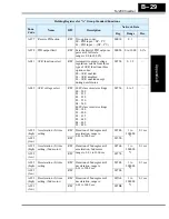
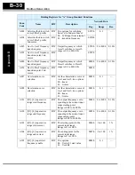
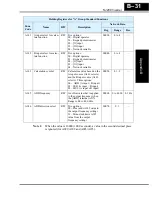
List of Holding Registers
Func.
Code
Name
R/W
Description
Network Data
Reg.
Range
Res.
Содержание SJ200 Series
Страница 53: ...SJ200 Inverter Inverter Mounting and Installation 2 15 Dimensional drawings continued SJ200 007HFEF 007HFU ...
Страница 185: ...Inverter System Accessories In This Chapter page Introduction 2 Component Descriptions 3 Dynamic Braking 5 5 ...
Страница 207: ...Glossary and Bibliography In This Appendix page Glossary 2 Bibliography 8 A ...
Страница 254: ...Drive Parameter Settings Tables In This Appendix page Introduction 2 Parameter Settings for Keypad Entry 2 C ...
Страница 265: ...CE EMC Installation Guidelines In This Appendix page CE EMC Installation Guidelines 2 Hitachi EMC Recommendations 6 D ...
Страница 269: ...SJ200 Inverter Appendix D D 5 L1 L2 L3 PE SJ200 inverter with book type filter M 3 ...


