Using Intelligent Output Terminals
Oper
ations
and Monitor
ing
4–50
Option
Code
Terminal
Symbol
Function Name
Output
State
Description
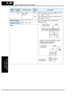
09
LOG
Logic Output
Function
ON
when the Boolean operation specified by C143
has a logical “1” result
OFF
when the Boolean operation specified by C143
has a logical “0” result
Valid for outputs:
11, 12, AL0 – AL2
Required settings:
C141, C142, C143
Notes:
RY
+
–
12 11
L
H O OI
FM CM2
Example (requires output configuration—
see page
Inverter output
terminal circuit
LOG
Example for terminals [AL0], [AL1], [AL2]
(requires output configuration—
see pages
AL0
AL2
AL1
Inverter logic
circuit board
See I/O specs
on page
LOG
Load
Power
supply
Содержание SJ200 Series
Страница 53: ...SJ200 Inverter Inverter Mounting and Installation 2 15 Dimensional drawings continued SJ200 007HFEF 007HFU ...
Страница 185: ...Inverter System Accessories In This Chapter page Introduction 2 Component Descriptions 3 Dynamic Braking 5 5 ...
Страница 207: ...Glossary and Bibliography In This Appendix page Glossary 2 Bibliography 8 A ...
Страница 254: ...Drive Parameter Settings Tables In This Appendix page Introduction 2 Parameter Settings for Keypad Entry 2 C ...
Страница 265: ...CE EMC Installation Guidelines In This Appendix page CE EMC Installation Guidelines 2 Hitachi EMC Recommendations 6 D ...
Страница 269: ...SJ200 Inverter Appendix D D 5 L1 L2 L3 PE SJ200 inverter with book type filter M 3 ...

