background image

HITACHI PROGRAMMABLE CONTROLLER


APPLICATION MANUAL

NJI-350B (X)

Содержание HIDIC MICRO-EH

Страница 1: ...HITACHI PROGRAMMABLE CONTROLLER APPLICATION MANUAL NJI 350B X ...

Страница 2: ...rior to installation and or operation of the equipment Hitachi Ltd constantly strives to improve its products and the equipment and the manual s that describe it may be different from those already in your possession If you have any questions regarding the installation and operation of the equipment or if more information is desired contact your local Authorized Distributor or Hitachi Ltd IMPORTAN...

Страница 3: ... sale of this PLC This warranty shall not apply to this PLC or any part hereof which has been subject to accident negligence alteration abuse or misuse Hitachi makes no warranty whatsoever in respect to accessories or parts not supplied by Hitachi The term original purchaser as used in this warranty shall be deemed to mean that person for whom the PLC in originally installed In no event whether as...

Страница 4: ...te at the time they were approved for printing Since Hitachi Ltd Incorporated constantly strives to improve all its products we reserve the right to make changes to equipment and or manuals at any time without notice and without incurring any obligation other than as noted in this manual Hitachi Ltd assumes no responsibility for errors that may appear in this manual As the product works with user ...

Страница 5: ...ked with may result in major accidents Both of these items contain important safety information so be sure to follow them closely Icons for prohibited items and required items are shown below Indicates a prohibited item item that cannot be performed For example when open flames are prohibited is shown Indicates a required item item that must be performed For example when grounding must be performe...

Страница 6: ...e emergency stop circuit interlock circuit and other related circuits external to the programmable controller referred to as the PLC in this document Otherwise a failure in the PLC may damage the equipment or result in a serious accident Never interlock the unit with the external load via the relay drive power supply of the relay output module CAUTION Before performing program change forced output...

Страница 7: ...rt circuit the battery There is a risk of an explosion or fire PROHIBITED Never disassemble or modify the unit These actions may result in a fire malfunction or failure CAUTION Be sure to turn off the power supply before removing or attaching the module unit Otherwise it may result in an electric shock malfunction or failure ...

Страница 8: ...of Timer counter number 2000 11 NJI 350 X 2 Postscript of battery error detection 3 2 chapters item number 26 15 chapters 4 Correct a description of digital filter 8 7 chapters Addition of appendix 3 2000 12 NJI 350A X 3 28 points expansion units added Analog expansion module added Circuit diagram added in chapter 3 FUN 5 TRNS RECV command added in chapter 5 2003 10 NJI 350B X ...

Страница 9: ...logue Input Specifications 3 14 3 3 9 Interrupt Input Specifications 3 14 3 3 10 Backup 3 14 3 3 11 Expansion 3 14 3 3 12 Clock Function 3 15 3 3 13 Power Supply for Sensor 3 16 Chapter 4 Product lineup and wiring 4 1 to 4 18 4 1 Product lineup 4 1 4 2 10 Point Basic Unit 4 3 4 3 14 Point Basic Unit 4 4 4 4 23 Point and 28 Point Basic Unit 4 5 4 5 Expansion Unit 4 6 4 6 Terminal Layout and Wiring ...

Страница 10: ...unter 8 8 8 3 High Speed Counter Two Phase Counter 8 10 8 3 1 Operation of the Two Phase Counters 8 10 8 3 2 Setting of Two Phase Counter 8 13 8 4 PWM Output 8 15 8 4 1 Operation of PWM Output 8 15 8 4 2 Setting of PWM Output 8 16 8 5 Pulse Train Output 8 18 8 5 1 Operation of Pulse Output 8 18 8 5 2 Setting of Pulse Output 8 19 8 6 Interrupt Input 8 21 8 7 Digital Filter 8 21 8 8 Potentiometers 8...

Страница 11: ... Chapter 12 Error Code List and Special Internal Outputs 12 1 to 12 14 12 1 Error Codes 12 1 12 2 Syntax and Assembler Error Codes 12 3 12 3 Operation Error Codes 12 4 12 4 Bit Special Internal Output Area 12 5 12 5 Word Special Internal Output Area 12 9 Chapter 13 Troubleshooting 13 1 to 13 16 13 1 Error Display and Actions 13 1 13 2 Checklist when Abnormality Occurred 13 5 13 3 Procedures to Sol...

Страница 12: ...MEMO ...

Страница 13: ...rminal blocks and installation on a DIN rail All models of the MICRO EH series support the DIN rail so that the PLC can easily be mounted and dismounted In addition the I O section of the 14 point PLC or more utilizes a removable terminal block Thus erroneous and faulty wiring that may occur when connecting to external devices can be reduced 6 Remote maintenance through modem connection Communicat...

Страница 14: ...Chapter 1 Features 1 2 MEMO ...

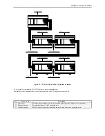
Страница 15: ...ne type programmable controller and has the following system configuration Figure 2 1 10 point type system configuration diagram Figure 2 2 14 point type system configuration diagram 1 Basic unit 1 Basic unit 3 Expansion cable 3 Expansion cable 3 Expansion cable 3 Expansion cable 2 Expansion unit 2 Expansion unit 2 Expansion unit 2 Expansion unit ...

Страница 16: ...ion for combination of 14 23 28 points and basic expansion unit 14 points basic unit can handle any type of expansion units and 23 28 points basic unit as well No Device name Description 1 Basic unit Calculates imports inputs and controls outputs according to the contents of user programs 2 Expansion unit 14 points digital unit 4 in 2 out analog unit 3 Expansion cable Cable for connecting the basi...

Страница 17: ...ambient humidity 5 to 95 RH no condensation Storage ambient humidity 5 to 95 RH no condensation Vibration proof Conforms to JIS C 0911 Noise resistance Noise voltage 1 500 Vpp Noise pulse width 100 ns 1 µs Noise created by the noise simulator is applied across the power supply module s input terminals This is determined by our measuring method Based on NEMA ICS 3 304 Static noise 3 000 V at metal ...

Страница 18: ...2C RS 485 RS 422 only the 23 point and 28 point types with RS 485 RS 422 5 Expansion connector basic unit and expansion unit This allows installation of additional input output except for 10 point type 6 Terminal block basic unit and expansion unit This performs the connections for supplying power and for handling signals with the control object 3 Number of I O points The number of points that can...

Страница 19: ...ge during power failure When stopping operation leave the internal information as is turn off the outputs and then stop the operation 6 When the power has been cut off for longer than the time allowed for the momentary power failure then depending on the system load status either operation continues or the system perceives that a power shut off has occurred and restarts operation To resume operati...

Страница 20: ... point type is not supported 15 Self diagnosis Self diagnostic tests for the following items are performed 1 Microcomputer check 2 System program area check 3 Memory check 4 User program check 5 Internal output area check 6 Mounted I O check 16 Abnormal handling When a problem occurs the error code that indicates the error description is output to special internal output WRF000 as a hexadecimal va...

Страница 21: ...it The resolution is 12 bits and it can be used by either selecting a current input between 0 and 20 mA or a voltage input between 0 and 10 V 24 Analogue output The analogue output function is available in the 23 point type and analog exp unit The resolution is 12 bits and it can be used by either selecting a current output between 0 and 20 mA or a voltage output between 0 and 10 V 25 Potentiomete...

Страница 22: ... arithmetic application control FUN command etc I O processing system Refresh processing I O processing specifications External I O Maximum number of points 10 points 126 points 135 points 140 points Bit 1 984 points R0 to R7BF Internal output Word 4 096 words WR0 to WRFFF Bit 64 points R7C0 to R7FF Special Word 512 words WRF000 to WRF1FF Bit word shared 16 384 points 1 024 words M0 to M3FFF WM0 t...

Страница 23: ...connection 10 point type fixed type terminal block 14 23 28 point types Removable type screw terminal block M3 1 Common terminals are separated each other 2 AC input Item Specification Circuit diagram Input voltage 100 to 120 V AC Allowable input voltage range 85 to 132 V AC 50 5 to 60 5 Hz Input impedance Approx 14 6 kΩ 60 Hz Approx 17 6 kΩ 50 Hz Input current Approx 7 mA RMS 100 V AC 60 Hz ON vo...

Страница 24: ...t response time ON OFF 0 1 ms max 24 V DC 0 2 A Number of output points 1 Number of common 1 Surge removing circuit None Fuse None Insulation system Photocoupler insulation Output display LED green External connection Removable type screw terminal block M3 External power supply 1 to V terminal Not necessary 30 to 16 V DC Insulation 1500 V or more external internal 500 V or more external external O...

Страница 25: ...rminals externally See 4 6 Terminal Layout and Wiring 3 DC output HCDC High Current Y100 Y101 of EH D14DT DTP Y100 Y101 Y110 and Y111 of EH D28DT DTP Y 016 Y 017 of EH D14EDT D14EDTP Item Specification Circuit diagram Output specification Transistor output Rated load voltage 24 12 V DC 10 15 Minimum switching current 1 mA Leak current 0 1 mA max 1 circuit 1A 24 V DC Maximum load current 1 common 3...

Страница 26: ...DC between the V and C terminals externally See 4 6 Terminal Layout and Wiring 5 DC output ESCP type LCDC Low Current Y102 Y105 of EH D14DTPS Y104 Y111 of EH D28DTPS Y 018 Y 021 of EH D14EDTPS Y 020 Y 027 of EH D28EDTPS Item Specification Circuit diagram Output specification Transistor output Rated load voltage 24 12 V DC 10 15 Minimum switching current 10 mA Leak current 0 1 mA max 1 circuit 0 7 ...

Страница 27: ... in Chapter 10 for the details 7 AC output SSR Item Specification Circuit diagram Output specification Triac output Rated voltage 100 240 V AC Output voltage 100 15 to 240 10 V AC 50 5 to 60 5 Hz 1 circuit 0 5 A 240 V AC Maximum load current 1 common 2 A Minimum load current 100 mA Maximum leakage current 1 8 mA 115 V AC max 3 5 mA 230 V AC max Maximum inrush current 5 A at 1 cycle or less point 1...

Страница 28: ...2 24 V 12 24 V Minimum load current 1 mA PWM max output frequency 1 2 kHz total channels Pulse train max output frequency 1 5 kHz total channels Pulse acceleration deceleration By FUN 151 1 Relay outputs cannot keep up with high frequencies these outputs should be used at the operating frequency upon confirmation 3 3 6 Analogue Input Specifications Module type 23 points module Analog exp unit Inpu...

Страница 29: ... 38mA max Resolution 12 bits Accuracy 1 of full scale Current output Allowable load Output allowable capacity Output allowable inductance 10 to 500 Ω Maximum 2000 pF Maximum 1 H Voltage output Allowable load Output allowable impedance Maximum 10 kΩ Maximum 1 µF Circuit diagram 23 points type Circuit diagram Analog expansion unit VO7 IO7 OC7 VO6 IO6 OC6 Voltage Current Internal circuit Voltage Curr...

Страница 30: ...due to hardware modification Battery can be mounted inside of front cover Battery is available only for 23 point and 28 point types If the calendar clock function is used with the 23 point or 28 point type be sure to use the battery 2 Capacitor 14 point type Data can be kept for 72 hours at 25 C by the capacitor 23 and 28 point types Data can be kept for 24 hours at 25 C by the capacitor Please no...

Страница 31: ...y 1 and the second digits are set to 00 4 Special internal output definitions Operation bits I O number Name Description R7F8 Request to read calendar and clock data Calendar and clock data is read out to WRF01B F01F R7F9 Request to write calendar and clock data Calendar and clock data in WRF01B F01F is written to the current data in WRF00B F00F R7FA Clock 30 seconds adjustment request Sets the se...

Страница 32: ...nput part of this unit the remaining can be used as power supply for the sensors The following current I can be supplied as power supply for the sensors 1 EH 14 14 point type basic unit EH 14E 14 point type extension unit I 350 mA 7 5 mA x number of input points that are turned on at the same time 2 EH A28DR 28 point type basic unit EH A23DR 23 point type basic unit I 280 mA 7 5 mA x number of inp...

Страница 33: ...ink 1 X48 Y32 empty16 EH D28DRP DC power DC input 16 Relay output 11 Transistor output source 1 X48 Y32 empty16 EH A28DRT AC power DC input 16 Relay output 11 Transistor output sink 1 X48 Y32 empty16 EH A28DRP AC power DC input 16 Relay output 11 Transistor output source 1 X48 Y32 empty16 EH A28DR AC power DC input 16 Relay output 12 X48 Y32 empty16 EH A28AS AC power AC input 16 SSR output 12 X48 ...

Страница 34: ... Form Specification Remarks EH MCB10 Length 1 m basic unit exp unit exp unit exp unit Total 2 m Cable for connecting basic unit and expansion unit EH MCB05 Length 0 5 m basic unit exp unit exp unit exp unit Total 2 m EH MCB01 Length 0 1 m basic unit exp unit exp unit exp unit Total 2 m Conversion cable for connecting peripheral units EH RS05 Length 0 5 m Peripheral equipment GPCB02H Length 2 m bet...

Страница 35: ...al port 1 Serial port for connecting the peripheral units Communication speed is fixed as 4800 bps The communication specification is set to port 1 See Chapter 11 5 RUN input External input to control the PLC s RUN STOP When 24 V DC is loaded to the RUN terminal and common terminal C the PLC is set to the RUN state See Chapter 10 6 Input terminals Terminals for wiring the external input units One ...

Страница 36: ...an be used The communication specification is set to port 1 See Chapters 8 and 11 5 Input terminals Terminals for wiring the external input units Recommended terminals are shown in the figure to the right One piece of AWG14 to AWG22 2 1 to 0 36 mm2 or two pieces of AWG16 to AWG22 1 3 to 0 36 mm2 per terminal may be wired See Chapter 10 Make sure that the terminals will not disengage due to loose s...

Страница 37: ... 11 5 Input terminals Terminals for wiring the external input units Recommended terminals are shown in the figure to the right One piece of AWG14 to AWG22 2 1 to 0 36 mm2 or two pieces of AWG16 to AWG22 1 3 to 0 36 mm2 per terminal may be wired See Chapter 10 Make sure that the terminals will not disengage due to loose screws Recommended 6 Output terminals Terminals for connecting the external loa...

Страница 38: ... normal operation 3 Expansion cover Left side Cover for expansion connector Used when connecting to the expansion cable from the front unit See Chapter 10 4 Input terminals Terminals for wiring the external input units Recommended terminals are shown in the figure to the right One piece of AWG14 to AWG22 2 1 to 0 36 mm2 or two pieces of AWG16 to AWG22 1 3 to 0 36 mm2 per terminal may be wired See ...

Страница 39: ...pply EH D10DR Since the DC input is bidirectional it is possible to reverse the polarity of the power supply 5 4 C0 3 2 RUN 1 0 NC V0 C0 3 2 1 24 V 0 0 V Load power supply 12 24V DC Power supply 24V DC Input power supply 24 V DC Power supply 24V DC Load power supply 24V DC 100 240V AC Input power supply 24V DC In case of EH D10DTP In case of EH D10DT 5 4 C0 3 2 RUN 1 0 NC C0 3 2 1 0 24V NC 0V ...

Страница 40: ...sible to reverse the polarity of the power supply AC power supply 100 240V AC Input power supply 24V DC DC power supply 24V DC Load power supply 24V DC 100 240V AC 0 24 0V 2 1 C0 3 5 4 7 6 C1 AC AC C0 0 C1 1 3 2 5 4 C2 Input Output 0V 24V AC power supply 100 240V AC Input power supply 24V DC DC power supply 24V DC Load power supply 24V DC 100 240V AC 0 24 0V 2 1 C0 3 5 4 7 6 C1 AC AC C0 16 C1 17 1...

Страница 41: ...EH D14DTP Load power supply 100 240V AC Power supply for input 100 115V AC Power supply 100 240V AC 0 24 0V 2 1 C0 3 5 4 7 6 C1 AC AC 0 NC C0 1 3 2 5 4 C1 Input Output Load power supply 12 24V DC Power supply for input 24V DC Power supply 24V DC 0 0V 2 1 C0 3 5 4 7 6 C1 0V 24V 1 0 2 NC 4 3 V0 5 C0 24 Input Output Load power supply 12 24V DC Power supply 24V DC 0V 24V 1 0 2 NC 4 3 V0 5 C0 Output ...

Страница 42: ... reverse the polarity of the power supply EH D14EDT The input wiring is the same as EH D14EDTP Load power supply 12 24V DC Power supply 24V DC 0V 24V 17 16 18 NC 20 19 V0 21 C0 Load power supply 12 24V DC Power supply 24V DC 0 24 0V 2 1 C0 3 5 4 7 6 C1 0V 24V 17 16 18 NC 20 19 V0 21 C0 Input Output Output ...

Страница 43: ... case of analog current input please set the following value in WRF06E WRF06E ch 0 ch 1 H0000 Voltage Voltage H4000 Voltage Current H8000 Current Voltage HC000 Current Current Please refer to Chapter 8 9 0 24 0V 2 1 C0 3 5 4 7 6 C1 AC AC C0 0 1 V0 3 2 C1 4 5 C3 6 C2 C4 7 9 8 IC VC IO VO 9 8 C2 11 10 IN1 12 IN1JP IN1 IN2 IN2 IN2JP C5 Input Output AC AC C0 0 1 NC 2 Output 0V 24V 0 1 V0 2 Output C0 T...

Страница 44: ...The input wiring is the same as EH A28DRP TR output power supply 16 30V DC Load power supply 24V DC 100 240V AC Power supply 100 240V AC Power supply for input 24V DC TR output power supply 16 30V DC Power supply 24V DC Power supply 100 240V AC 0 24 0V 2 1 C0 3 5 4 7 6 C1 AC 0 1 V0 3 2 C1 4 5 C3 6 C2 C4 7 C5 8 10 C6 11 C6 10 9 8 C2 11 12 C2 14 13 C3 15 C3 9 AC C0 Input Output AC AC C0 0 1 NC 2 Out...

Страница 45: ...upply 100 240V AC Power supply for input 24V DC Load power supply 12 24V DC Power supply 24V DC Power supply 24V DC 0 NC NC 2 1 C0 3 5 4 7 6 C1 AC NC C0 1 3 2 5 4 C1 C2 NC NC 6 C2 C3 7 8 10 9 11 8 C2 C2 10 9 C3 11 12 C3 13 C3 AC 0 14 15 Input Output 0 24 0V 2 1 C0 3 5 4 7 6 C1 0V 0 2 NC 4 3 V0 5 C0 C1 C1 NC V1 V1 7 6 9 10 NC 11 10 9 8 C2 11 12 C2 14 13 C3 15 C3 8 24V 1 Input Output 0V 0 2 NC 4 3 V...

Страница 46: ...4 7 6 C1 AC 0 1 NC 3 2 C1 4 5 C3 6 C2 C4 7 C5 8 10 C6 11 C6 10 9 8 C2 11 12 C2 14 13 C3 15 C3 9 AC C0 Input Output Load power supply 24V DC 100 240V AC Power supply 100 240V AC Power supply for input 24V DC 0 24 0V 2 1 C0 3 5 4 7 6 C1 AC 16 17 NC 19 18 C1 20 21 C3 22 C2 C4 23 C5 24 26 C6 27 C6 10 9 8 C2 11 12 C2 14 13 C3 15 C3 25 AC C0 Input Output Load power supply 24V DC 100 240V AC Power supply...

Страница 47: ...voltage or current independently Power supply 100 240V AC IN1JP IN1 IN1 IN2 IN2 IN3 IN2JP IN3JP IN3 IN4 IN4 IN4JP AC AC OC6 NC VO6 IO6 IO7 OC7 NC VO7 NC _ _ Voltage input 4 Voltage output 2 Power supply 24V DC IN1JP IN1 IN1 IN2 IN2 IN3 IN2JP IN3JP IN3 IN4 IN4 IN4JP 0V 24V OC6 NC VO6 IO6 IO7 OC7 NC VO7 NC Input and output can be configured as voltage or current independently Current input 4 Current...

Страница 48: ...00 0 16 0 6 EH A14AS 380 0 1 15 0 06 40 EH A23DRP DRT 600 0 2 15 0 06 40 EH D23DRP 500 0 2 0 6 EH D28DT DTP DTPS 500 0 2 0 6 EH A28DRP DRT 600 0 1 15 0 06 40 EH A28DR 600 0 2 15 0 06 40 EH D28DRP DRT 500 0 3 0 6 EH D28DR 500 0 3 0 6 EH A28AS 600 0 2 15 0 06 40 EH D14EDT EDTP EDTPS 300 0 16 0 6 EH A14EDR 400 0 1 15 0 06 40 EH D14EDR 300 0 16 0 6 EH D28EDT EDTPS 500 0 2 0 6 EH A28EDR 600 0 2 15 0 06...

Страница 49: ...ng 4 17 4 8 Exterior Dimensions 1 10 point type Unit mm 2 14 point type 14 point expansion unit Analog expansion unit 3 23 point 28 point types and 28 point expansion 75 65 47 70 80 4 4 8 95 85 80 90 76 4 8 8 4 150 140 80 90 76 4 8 8 4 ...

Страница 50: ...Chapter 4 Product lineup and wiring 4 18 MEMO ...

Страница 51: ... when the BCD was abnormal data etc When there is no data error it is set to 0 ERR Error special internal output R7F3 Set to 1 when an error is generated when a control instruction and a special instruction are executed The error code is set in WRF015 When there are no errors the previous status is maintained SD Shift data special internal output R7F2 Performs shift in of the contents of SD by the...

Страница 52: ...ction z z z z z 0 9 2 6 ORI Logical NOR Indicates b contact parallel connection 7 NOT Logical NOT Reverses all operation results up to that point None z z z z z 0 8 2 8 DIF AND DIF Leading edge detection Indicates detection of the input rise DIF0 to DIF511 Decimal z z z z z 1 0 3 4 Number overlap not allowed DIF OR DIF 9 DFN AND DFN Trailing edge detection Indicates detection of the input fall DFN...

Страница 53: ...6 3 21 Relational box start and end Indicates start and end of a comparison box None z z z z z 0 8 0 2 Basic instructions timer counter R7F4 R7F3 R7F2 R7F1 R7F0 Process time µ s Classification Item number Ladder symbol Instruction symbol Instruction name Process descriptions I O types used DERERR SD V C MICRO EH Steps Remarks Timer 22 TD OUT TD On delay timer Indicates an on delay timer operation ...

Страница 54: ...1 s2 Relational box When s1 s2 Noncontinuity When s1 s2 Continuity z z z z z 26 8 5 6 7 8 1 2 Upper case W AND s1 s2 Word WX WY WR WM Timer Counter Double word DX DY DR DM Constant 34 5 Lower case DW OR s1 s2 31 LD s1 S s2 Signed Relational box When s1 s2 Noncontinuity When s1 s2 Continuity s1 and s2 are compared as signed 32 bit binary DX DY DR DM Constant z z z z z 34 5 5 6 7 8 2 AND s1 S s2 OR ...

Страница 55: ...l box When s1 s2 Noncontinuity When s1 s2 Continuity z z z z z 26 8 5 6 7 8 1 2 Upper case W AND s1 s2 Word WX WY WR WM Timer Counter Double word DX DY DR DM Constant 42 Lower case DW OR s1 s2 35 LD s1 S s2 Signed Relational box When s1 s2 Continuity When s1 s2 Noncontinuity s1 and s2 are compared as signed 32 bit binary DX DY DR DM Constant z z z z z 37 5 5 6 7 8 2 AND s1 S s2 OR s1 S s2 1 In the...

Страница 56: ...pper case W Lower case DW Mathematical operation 4 d s1 s2 Binary subtraction d s1 s2 z z z 41 58 4 6 Upper case W Lower case DW 5 d s1 B s2 BCD subtraction d s1 s2 Word d WY WR WM s1 s2 WX WY WR WM Timer Counter Constant Double word d DY DR DM s1 s2 DX DY DR DM Constant z z z 104 163 4 6 Upper case W Lower case DW 6 d s1 x s2 Binary multiplication d s1 x s2 z z z z 43 112 4 6 Upper case W Lower c...

Страница 57: ...stant Double word d Y R M s1 s2 DX DY DR DM Constant z z z z z 60 48 4 6 Upper case W Lower case DW 16 d s1 S s2 Signed Relational expression When s1 s2 d 1 When s1 s2 d 0 s1 and s2 are compared as signed 32 bit binary Double word d Y R M s1 s2 DX DY DR DM Constant 108 6 17 d s1 s2 Relational expression When s1 s2 d 0 When s1 s2 d 1 Word d Y R M s1 s2 WX WY WR WM Timer Counter Constant Double word...

Страница 58: ... to bit n z z z z z 26 35 3 3 Upper case W Lower case DW 2 BRES d n Bit reset n 0 d Sets 0 to bit n z z z z z 29 38 3 3 Upper case W Lower case DW Bit operations 3 BTS d n Bit test n 0 d Acquires the value in bit n to C R7F0 Word d WY WR WM TC n 0 15 WX WY WR WM TC Constant Double word d DY DR DM n 0 31 WX WY WR WM TC Constant z z z z 31 38 3 3 Upper case W Lower case DW 4 SHR d n Shift right Shif...

Страница 59: ... n bit or word range from I O number d Bit d R M s X Y R M Constant n 0 255 WX WY WR WM TC Constant z z z z 80 4 3 Upper case B Word d WR WM s n 0 255 WX WY WR WM TC Constant 73 4 Lower case W 14 XCG d1 d2 n Block exchange Exchanges the n bit or word range from I O number d1 and the n bit or word range from I O number d2 Bit d1 d2 R M n 0 255 WX WY WR WM TC Constant z z z z 139 4 3 Upper case B Wo...

Страница 60: ...lasts for the amount of nth power of 2 and stores it in I O number d If multiple bits that contain 1 exist the one with the upper bit locations will be encoded d WY WR WM s R M n Constant 1 8 z z z 128 4 3 3 Processing time when n 1 R7F4 R7F3 R7F2 R7F1 R7F0 Process time µ s Classification Item number Ladder symbol Instruction symbol Instruction name Process descriptions I O types used DERERR SD V ...

Страница 61: ...ine of the same No n n Constant 0 99 z 1 z z z 24 2 9 SB n Start subroutine Indicates the start of No n subroutine n Constant 0 99 z 1 z z z 0 5 1 10 RTS RETURN SUBROUTIN Returns from subroutine None z z z z z 25 1 11 INT n Start interrupt scan Indicates the start of No n interrupt scan n Constant 0 2 16 19 20 27 z z z z z 0 5 1 12 RTI RETURN INTERRUPT Returns from interrupt scan None z z z z z 0 ...

Страница 62: ...2 3 10 FUN 145 s High speed counter current value clear Clears the count value of the specified counter number s WR WM z z z z 157 3 11 FUN 146 s High speed counter preset The on preset value and off preset value will be set according to the preset specifications in respect to the specified counter number s WR WM s 1 WR WM s 2 WR WM z z z z 162 3 12 FUN 147 s PWM operation control Starts PWM outpu...

Страница 63: ... Instruction Specifications 5 13 5 3 Instruction Specification Details 1 Basic instructions 2 Arithmetic instructions 3 Application instructions 4 Control instructions 5 Transfer instructions 6 FUN instructions ...

Страница 64: ...the continuity state when input is off Notes Edge detection DIF DFN cannot be used in respect to LDI Pay close attention if the external output is to be monitored when counter input coincidence output PWM output or pulse output is set with the PI O function Y100 WR0 WR0 1 DIF1 Y100 will not change while monitored It will remain the same value previously set using functions such as set reset For ex...

Страница 65: ...on Notes Edge detection DIF DFN cannot be used in respect to ANI Pay close attention if the external output is to be monitored when counter input coincidence output PWM output or pulse output is set with the PI O function R0 WR0 WR0 1 Y100 DIF1 Y100 will not change when monitored It will remain the same value previously set using functions such as set reset For example if Y100 is off the Y100 stat...

Страница 66: ... previous operation result and the b contact operation Notes Edge detection DIF DFN cannot be used in respect to ORI Pay close attention if the external output is to be monitored when counter input coincidence output PWM output or pulse output is set with the PI O function R0 WR0 WR0 1 DIF1 Y100 Y100 will not change when monitored It will remain the same value previously set using functions such a...

Страница 67: ...f steps 0 8 Condition Steps NOT 2 Bit Word Double word Usable I O X Y R M TD SS CU CT WX WY WR WM TC DX DY DR DM Constant Other Function Reverses the operation result obtained up to that point Program example X00000 R100 LD AND NOT OUT X00000 X00001 R100 X00001 Program description When input X00000 and input X00001 are both on the operation is 1 but due to the calculation turns into 0 and R100 tur...

Страница 68: ...M TC DX DY DR DM Constant Other n Number 0 to 511 Decimal Function Detects the rise of an input signal and retains the operation result only for one scan indicates the display when the Ladder Editor is used Notes DIF number may not be overlapped However no error is generated even if overlapped numbers are used DIF cannot use the b contact Program example X00000 R123 LD AND OUT X00000 DIF0 R123 DIF...

Страница 69: ... WR WM TC DX DY DR DM Constant Other n Number 0 to 511 Decimal Function Detects the fall of an input signal and retains the operation result only for one scan indicates the display when the Ladder Editor is used Notes DFN number may not be overlapped However no error is generated even if overlapped numbers are used DFN cannot use the b contact Program example X00000 R124 LD AND OUT X00000 DFN0 R12...

Страница 70: ...M TC DX DY DR DM Constant Other n I O number Function Switches on the coil when the operation result obtained up to that point is 1 Switches off the coil when the operation result obtained up to that point is 0 Notes L becomes the internal output when link modules are not used Program example X00000 X00001 Y00100 Y00101 LD OUT LD OUT OUT X00000 Y00100 X00001 Y00101 Y00102 Y00102 Program descriptio...

Страница 71: ...hed on will not be switched off even if the operation result is 0 n RES RES n Switches off the device when the operation result obtained up to that point is 1 indicates the display when the Ladder Editor is used Notes When a set reset coil is used on a multi layer coil it must be set to the highest level or an arbitrary contact must be entered immediately before the use Example of OK Example of NG...

Страница 72: ...nput to the circuit sandwiched by the master control set MCS n and reset MCR n An AND operation is performed with respect to each input and MCS The master control can be used up to eight layers indicates the display when the Ladder Editor is used Notes Always use the master control MCS and MCR in pairs Program example X00000 X00001 MCS1 Y00100 MCR1 LD X00000 MCS1 LD X00001 OUT Y00100 MCR1 MCS0 MCS...

Страница 73: ...Read 0 MPP Clear Bit Word Double word Usable I O X Y R M TD SS CU CT WX WY WR WM TC DX DY DR DM Constant Other Function X00100 Y00101 LD X00100 MPS AND R001 MPS OUT Y00101 MPP AND R002 OUT Y00102 MRD AND R003 OUT Y00103 MPP AND R004 OUT Y00104 R001 Y00102 R002 Y00103 R003 Y00104 R004 MPS stores the previous operation result Push MRD reads the results stored by the MPS and continues operation MPP r...

Страница 74: ...on column DER ERR SD V C z z z z z Instruction format Number of steps Condition Steps ANB 0 Bit Word Double word Usable I O X Y R M TD SS CU CT WX WY WR WM TC DX DY DR DM Constant Other Function X00001 Y00100 LD X00001 LD R010 OR R011 ANB LD M0020 AND M0021 OR M0022 ANB OUT Y00100 R010 M0020 M0021 R011 M0022 This instruction is used to perform AND operation with respect to the logical operation bl...

Страница 75: ... Function column DER ERR SD V C z z z z z Instruction format Number of steps 0 7 Condition Steps ORB 1 Bit Word Double word Usable I O X Y R M TD SS CU CT WX WY WR WM TC DX DY DR DM Constant Other Function X00000 Y00105 LD X00000 LD R010 LD R011 AND R012 ORB OR X00001 ANB OUT Y00105 R010 R011 X00001 R012 This instruction is used to perform OR operation with respect to the logical operation blocks ...

Страница 76: ...uction format Number of steps 0 6 Condition Steps 3 Bit Word Double word Usable I O X Y R M TD SS CU CT WX WY WR WM TC DX DY DR DM Constant Other Function Indicates the start and end of the processing box X00001 WY0010 WX0000 LD X00001 WY0010 WX0000 In the above example the operation inside the processing box will be executed when input X00001 is on Parallel connection of processing box or coil is...

Страница 77: ...er format Condition code Processing time µs Remark R7F4 R7F3 R7F2 R7F1 R7F0 Average Maximum DER ERR SD V C z z z z z Instruction format Number of steps 0 8 Condition Steps 0 Bit Word Double word Usable I O X Y R M TD SS CU CT WX WY WR WM TC DX DY DR DM Constant Other Function Indicates the start and end of the relational box z z ...

Страница 78: ...and does not exceed 65535 decimal If the progress value is updated during RUN the operation will be performed using the new progress value at that point If an I O is set for the set value the set value can be changed during operation by changing the I O value since the set values are updated during each scan Notes The 01s time base can only be used for timer numbers 0 to 63 64 points The 1 s and 1...

Страница 79: ...the TD progress value is cleared 3 TD10 turns on when progress value set value 4 While X00000 is on the progress value increases but will not increase exceeding 65535 5 When X00000 turns off TD10 also turns off and the progress value is cleared Example using word I O as the set value When RUN is commenced the set value is set to the word I O Or the word I O for the set value is designated to store...

Страница 80: ...5 decimal If the progress value is updated during RUN the operation will be performed using the new progress value at that point If an I O is set for the set value the set value can be changed during operation by changing the I O value since the set values are updated during each scan Notes The 01 s time base can only be used for timer numbers 0 to 63 64 points The 1 s and 1s time bases can be use...

Страница 81: ...e ignored because it uses edge trigger 3 SS11 is turned on at the leading edge of X00001 again and the progress value is updated 4 When the leading edge of X00001 is detected while the progress value does not reach the set value the single shot timer is triggered again and the progress value returns to 0 then starts increasing The SS11 remains on Example using word I O as the set value When RUN is...

Страница 82: ...hile the system is running the operation will be performed using the new progress value at that point If an I O is set for the set value the set value can be changed during operation by changing the I O value since the set values are updated during each scan Notes A maximum of 256 points can be used for the timers and counters TD SS CU CTU and CTD in total The timer numbers and counter numbers can...

Страница 83: ...s updated at the leading edge of X00005 3 Counter coil CU15 is turned on since the progress value set value 4 The count value will not exceed 65535 decimal 5 The progress value and counter coil are cleared by counter clear CL15 The clear is performed under the conditions set immediately prior to the execution of the counter coil instruction Example using word I O as the set value When RUN is comme...

Страница 84: ...ogress value is less than the set value When the counter clear CL n switches on the progress value is cleared to 0 and the coil switches off The progress value is set in TC n and the value will be in the range of 0 to 65535 decimal If the progress value is updated during RUN the operation will be performed using the new progress value at that point If an I O is set for the set value the set value ...

Страница 85: ... of X00007 2 The counter coil CT17 is turned on when the progress value set value 3 When the up coil and down coil startup conditions turn on simultaneously the progress value does not change 4 The progress value is down counted at the leading edge of X00008 5 The counter coil turns off when set value progress value 6 The progress value will not exceed 65535 decimal Also it will not be below 0 7 W...

Страница 86: ...er and switches off the timer coil In the case of WDT the time monitor check is performed see WDT for details In the case of counters the progress value is cleared and the counter coil is switched off The clearing operation is conducted immediately before execution of the counter or timer coil instruction indicated by the clear coil Example X00000 CL10 X00001 CU10 X00002 CL10 1 When X00000 is turn...

Страница 87: ...2 Function Ladder format s1 s2 s1 s2 s1 s2 Compares s1 and s2 as unsigned numbers and if s1 is equals to s2 it enters the continuity status on and if s1 is not equal to s2 enters the noncontinuity status off When s1 and s2 are words 0 to 65535 decimal or H0000 to HFFFF hexadecimal When s1 and s2 are double words 0 to 4294967295 decimal or H00000000 to HFFFFFFFF hexadecimal Notes Number of steps Wo...

Страница 88: ... 1 s2 Relational number 2 Function Ladder format s1 S s2 s1 S s2 s1 S s2 z Compares s1 and s2 as signed double word numbers and if s1 is equals to s2 it enters the continuity status on and if s1 is not equal to s2 enters the noncontinuity status off z s1 s2 2147483648 to 2147483647 decimal H80000000 to H7FFFFFFF hexadecimal b31 b0 Sign bit 0 Positive 1 Negative Cautionary notes Number of steps Dou...

Страница 89: ...r 2 Function Ladder format s1 s2 s1 s2 s1 s2 Compares s1 and s2 as unsigned numbers and if s1 is equals to s2 it enters the noncontinuity status off and if s1 is not equal to s2 enters the continuity status on When s1 and s2 are words 0 to 65535 decimal or H0000 to HFFFF hexadecimal When s1 and s2 are double words 0 to 4294967295 decimal or H00000000 to HFFFFFFFF hexadecimal Notes Number of steps ...

Страница 90: ... s2 Relational number 2 Function Ladder format s1 S s2 s1 s2 s1 s2 S S z Compares s1 and s2 as signed double word numbers and if s1 is equals to s2 it enters the noncontinuity status off and if s1 is not equal to s2 enters the continuity status on z s1 s2 2147483648 to 2147483647 decimal H80000000 to H7FFFFFFF hexadecimal b31 b0 Sign bit 0 Positive 1 Negative Cautionary notes Number of steps Doubl...

Страница 91: ...nction Ladder format s1 s2 s1 s2 s1 s2 Compares s1 and s2 as unsigned numbers and if s1 is less than s2 it enters the continuity status on and if s1 is greater than or equal to s2 enters the noncontinuity status off When s1 and s2 are words 0 to 65535 decimal or H0000 to HFFFF hexadecimal When s1 and s2 are double words 0 to 4294967295 decimal or H00000000 to HFFFFFFFF hexadecimal Notes Number of ...

Страница 92: ...lational number 2 Function Ladder format s1 S s2 s1 s2 s1 s2 S S z Compares s1 and s2 as signed double word numbers and if s1 is less than s2 it enters the continuity status on and if s1 is greater than or equal to s2 enters the noncontinuity status off z s1 s2 2147483648 to 2147483647 decimal H80000000 to H7FFFFFFF hexadecimal b31 b0 Sign bit 0 Positive 1 Negative Cautionary notes Number of steps...

Страница 93: ...tion Ladder format s1 s2 s1 s2 s1 s2 Compares s1 and s2 as unsigned numbers and if s1 is less than or equal to s2 it enters the continuity status on and if s1 is greater than s2 it enters the noncontinuity status off When s1 and s2 are words 0 to 65535 decimal or H0000 to HFFFF hexadecimal When s1 and s2 are double words 0 to 4294967295 decimal or H00000000 to HFFFFFFFF hexadecimal Notes Number of...

Страница 94: ...r 1 s2 Relational number 2 Function Ladder format s1 S s2 s1 S s2 s1 S s2 z Compares s1 and s2 as signed double word numbers and if s1 is less than or equal to s2 it enters the continuity status on and if s1 is greater than s2 it enters the noncontinuity status off z s1 s2 2147483648 to 2147483647 decimal H80000000 to H7FFFFFFF hexadecimal b31 b0 Sign bit 0 Positive 1 Negative Cautionary notes Num...

Страница 95: ... possible to use array variables for d and s When d is a word the constant is 0 to 65535 or 32768 to 32767 decimal H0000 to HFFFF or H8000 to H7FFF hexadecimal When d is a double word the constant is 0 to 4294967295 or 2147483648 to 2147483647 decimal H00000000 to HFFFFFFFF or H80000000 to H7FFFFFFF Notes When using an array variable DER is set to 1 if the usable I O number exceeds the maximum val...

Страница 96: ... of input X00000 2 The value of WX0000 is substituted into the WR number designated by WR0000 WM000 at the leading edge of input X00001 1 When WM000 H0010 it holds the same meaning as WR0010 WX0000 3 The word number of the I O advanced by the amount designated by WR0000 WM001 due to the I O assignment is substituted into WR0000 at the leading edge of input X00002 1 When WM001 H0010 it hods the sam...

Страница 97: ...he range of H0000 to HFFFF for word and H00000000 to HFFFFFFFF for double word Otherwise It is set to 1 C s1m x s2m s1m x dm s2m x dm The V flag is set to 1 if the operation result is meaningless as signed binary data and 0 if it is meaningful s1 s2 d V Positive Positive Positive 0 Positive Positive Negative 1 Positive Negative Positive Negative 0 Negative Positive Negative Positive 0 Negative Neg...

Страница 98: ...d as the BCD data The C flag is set to 1 if there is a digit increase and 0 if not The DER flag is set to 1 if the operation result s1 and s2 are invalid as the BCD data If so operation is not performed and the C flag retains the previous state without outputting to d If the s1 and s2 are valid as the BCD data the DER is set to 0 When s1 s2 are words 0000 to 9999 BCD When s1 s2 are double words 00...

Страница 99: ...ata The C flag is set to 1 if there is a digit decrease and 0 if not C s1m x s2m s1m x dm s2m x dm The V flag is set to 1 if the operation result is a meaningless signed binary data and 0 if it has meaning s1 s2 d V Positive Positive Positive Negative 0 Negative Negative Positive Negative 0 Positive Negative Positive 0 Positive Negative Negative 1 Negative Positive Positive 1 Negative Positive Neg...

Страница 100: ...hend Function Subtracts s2 from s1 as the BCD data and substitutes the result into d as the BCD data The C flag is set to 1 if there is a digit decrease and 0 if not The DER flag is set to 1 if s1 or s2 is not a valid BCD data If so operation is not performed and the C flag retains the previous state without outputting to d If the s1 and s2 are valid BCD data the DER is set to 0 Notes The combinat...

Страница 101: ... d lower digit in binary The DER flag is set to 1 if d 1 exceeds the usable I O range in this case only the lower word is substituted and 0 when it does not exceed MSB 0 MSB 0 d 0 MSB d 1 WR0010 WR0011 WR0012 WR0013 Example WR0012 WR0010 WR0011 DR0012 WR0011 DR0010 WR0010 WR0013 DR0012 WR0012 WR0015 DR0014 WR0014 WR0017 DR0016 WR0016 s2 s1 Example WR0014 DR0010 DR0012 Notes The combinations of d s...

Страница 102: ... is not performed Also if d 1 exceeds the usable I O range the DER flag is set to 1 and only the lower digit word is substituted The DER flag is set to 0 if s1 and s2 are valid BCD data and d 1 is within the usable I O range MSB 0 MSB 0 d 0 MSB d 1 WR0014 WR0015 WR0016 WR0017 Example WR0016 WR0014 Bx WR0015 DR0016 WR0019 DR0018 WR0018 WR0021 DR0020 WR0020 WR0023 DR0022 WR0022 WR0025 WR0024 s1 d 1 ...

Страница 103: ...y z The DER flag is 1 if d 1 exceeds the usable I O range in this case only the lower digit word is substituted and 0 when it does not 31 0 d d 1 Example D R0031 DR0026 S DR0028 s1 31 0 s2 Sign 63 0 Sign bit 3231 WR0027 WR0026 s1 DR0026 WR0029 WR0028 s2 DR0028 WR0032 WR0031 WR0034 WR0033 DR0031 DR0033 Sign The sign of the operation result is entered in the most significant bit z s1 s2 2147483648 t...

Страница 104: ...remainder is set in the special internal output WRF016 DRF016 in the case of double word The DER flag is set to 1 if s2 is 0 and the operation is not performed As long as s2 is not set to 0 the flag is set to 0 and the operation is performed WR0041 WR0040 WR0042 WRF016 Example WR0042 WR0040 WR0041 Example DR0047 DR0045 DR0043 WR0041 WR0043 DR0043 WR0046 WR0045 DR0045 WR0048 WR0047 DR0047 WRF017 WR...

Страница 105: ... internal output WRF016 DRF016 in the case of double word The DER flag is set to 1 if s1 or s2 is an invalid BCD data or when s2 is set to 0 In this case the operation is not performed If both s1 and s2 are valid BCD data and s2 is not set to 0 the operation is performed WR0050 WR0049 WR0051 WRF016 Example WR0051 WR0049 B WR0050 When s1 s2 are words 0000 to 9999 BCD When s1 s2 are double words 000...

Страница 106: ...special internal output DRF016 signed binary data z The DER flag is 1 if s2 is 0 and the operation is not performed As long as s2 is not 0 it is 0 and the operation is performed z The V flag is 1 when the quotient is a positive value and exceeds H7FFFFFFF Otherwise it is 0 Eexample DR0060 DR0056 S DR0058 WR0059 WR0058 DR0058 WR0057 WR0056 DR0056 DRF016 WR0061 WR0060 DR0060 WRF017 WRF016 z s1 s2 21...

Страница 107: ...C DX DY DR DM Constant Other d Substitution destination s1 Comparand s2 Relational number Function Obtains OR of s1 and s2 and substitutes the result into d s1 s2 d 0 0 0 0 1 1 1 0 1 1 1 1 Notes The combinations of d s1 and s2 are as follows d s1 s2 Bit Bit Bit Word Word Word Double word Double word Double word Program example WR0102 WR0100 OR WR0101 X00110 DIF110 LD X00110 AND DIF110 WR0102 WR010...

Страница 108: ... DX DY DR DM Constant Other d Substitution destination s1 Comparand s2 Relational number Function Obtains AND of s1 and s2 and substitutes the result into d s1 s2 d 0 0 0 0 1 0 1 0 0 1 1 1 Notes The combinations of d s1 and s2 are as follows d s1 s2 Bit Bit Bit Word Word Word Double word Double word Double word Program example WR0102 WR0100 AND WR0101 X00111 DIF111 LD X00111 AND DIF111 WR0102 WR01...

Страница 109: ... DR DM Constant Other d Substitution destination s1 Comparand s2 Relational number Function Obtains exclusive OR XOR of s1 and s2 and substitutes the result into d s1 s2 d 0 0 0 0 1 1 1 0 1 1 1 0 Notes The combinations of d s1 and s2 are as follows d s1 s2 Bit Bit Bit Word Word Word Double word Double word Double word Program example WR0102 WR0100 XOR WR0101 X00112 DIF112 LD X00112 AND DIF112 WR01...

Страница 110: ...double word 6 Bit Word Double word Usable I O X Y R M TD SS CU CT WX WY WR WM TC DX DY DR DM Constant Other d Substitution destination s1 Comparand s2 Relational number Function Substitutes 1 when s1 is equal to s2 and otherwise 0 into d assuming s1 and s2 as binary data Notes The combinations of d s1 and s2 are as follows d s1 s2 Bit Word Word Bit Double word Double word Program example M0000 WX0...

Страница 111: ...bstitution destination s1 Comparand s2 Relational number Function z Substitutes 1 when s1 is equal to s2 and otherwise 0 into d assuming s1 and s2 as signed binary data z s1 and s2 are both signed binary data When the most significant bit is 0 the value is positive when the most significant bit is 1 the value is negative s1 s2 2147483648 to 2147483647 decimal H80000000 to H7FFFFFFF hexadecimal b31...

Страница 112: ...le Word 6 Bit Word Double word Usable I O X Y R M TD SS CU CT WX WY WR WM TC DX DY DR DM Constant Other d Substitution destination s1 Comparand s2 Relational number Function Substitutes 1 when s1 is not equal to s2 and otherwise 0 into d assuming s1 and s2 as binary data Notes The combinations of d s1 and s2 are as follows d s1 s2 Bit Word Word Bit Double word Double word Program example Y00000 WR...

Страница 113: ...ion destination s1 Comparand s2 Relational number Function z Substitutes 1 when s1 is not equal to s2 and otherwise 0 into d assuming s1 and s2 as signed binary data z s1 and s2 are both signed binary data When the most significant bit is 0 the value is positive when the most significant bit is 1 the value is negative s1 s2 2147483648 to 2147483647 decimal H80000000 to H7FFFFFFF hexadecimal b31 b1...

Страница 114: ... word 6 Bit Word Double word Usable I O X Y R M TD SS CU CT WX WY WR WM TC DX DY DR DM Constant Other d Substitution destination s1 Comparand s2 Relational number Function Substitutes 1 when s1 is less than s2 and otherwise 0 into d assuming s1 and s2 as binary data Notes The combinations of d s1 and s2 are as follows d s1 s2 Bit Word Word Bit Double word Double word Program example R0 TC100 TC101...

Страница 115: ...stitution destination s1 Comparand s2 Relational number Function z Substitutes 1 when s1 is less than s2 and otherwise 0 into d assuming s1 and s2 as signed binary data z s1 and s2 are both signed binary data When the most significant bit is 0 the value is positive when the most significant bit is 1 the value is negative s1 s2 2147483648 to 2147483647 decimal H80000000 to H7FFFFFFF hexadecimal b31...

Страница 116: ...1 s is a double word 6 Bit Word Double word Usable I O X Y R M TD SS CU CT WX WY WR WM TC DX DY DR DM Constant Other d Substitution destination s1 Comparand s2 Relational number Function Substitutes 1 when s1 is less than or equal to s2 and otherwise 0 into d assuming s1 and s2 as binary data Notes The combinations of d s1 and s2 are as follows d s1 s2 Bit Word Word Bit Double word Double word Pro...

Страница 117: ...ination s1 Comparand s2 Relational number Function z Substitutes 1 when s1 is less than or equal to s2 and otherwise 0 into d assuming s1 and s2 as signed binary data z s1 and s2 are both signed binary data When the most significant bit is 0 the value is positive when the most significant bit is 1 the value is negative s1 s2 2147483648 to 2147483647 decimal H80000000 to H7FFFFFFF hexadecimal b31 b...

Страница 118: ...it location to be set The constant is set in decimal Function Sets the nth bit in the I O word or double word specified by d to 1 Other bit contents are unaltered 5 d 4 3 2 1 0 n 1 n 1 n 1 1 is set If d is a word Designates the bit location depending on the contents 0 to 15 of the lower 4 bits b3 to b0 of n WX WY WR WM TC Upper bits are ignored and considered as 0 The n constant can be set to 0 to...

Страница 119: ...t location to be reset The constant is set in decimal Function Sets the nth bit in the I O word or double word specified by d to 0 Other bit contents are unaltered 5 d 4 3 2 1 0 n 0 n 1 n 1 Reset to 0 If d is a word Designates the bit location depending on the contents 0 to 15 of the lower 4 bits b3 to b0 of n WX WY WR WM TC Upper bits are ignored and considered as 0 The n constant can be set to 0...

Страница 120: ... d and if the result is 1 1 is set to C R7F0 If the result is 0 C R7F0 is reset to 0 The contents of d remains unaltered 5 d C R7F0 4 3 2 1 0 n n 1 n 1 If d is a word Designates the bit location depending on the contents 0 to 15 of the lower 4 bits b3 to b0 of n WX WY WR WM TC Upper bits are ignored and considered as 0 The n constant can be set to 0 to 15 decimal If d is a double word Designates t...

Страница 121: ...t of DR0100 is set to 1 by the BSET at the leading edge of X00000 DR0100 00000000000000000000000000000000 b31 b20 b0 This bit is set to 1 Also the 20th bit of DR0102 is reset to 0 by BRES DR0102 11111111111111111111111111111111 b31 b20 b0 This bit is set to 0 Also the 20th bit of DR0104 is checked by BTS DR0104 01010101010101011010101010101010 b31 b20 b0 This bit is checked Since the 20th bit is 1...

Страница 122: ...R7F2 contents starting with the most significant bit Sets the content of the nth bit from the least significant bit in C R7F0 SD SD SD SD SD SD B C R7F0 SD R7F2 d B Least significant bit LSB Most significant bit MSB n bits n bits Before execution After execution If d is a word Designates the shift amount depending on the contents 0 to 15 of the lower 4 bits b3 to b0 of n WX WY WR WM TC Upper bits ...

Страница 123: ...he right a pulse input enters X1 There is a sensor on the left end of the conveyor and when a defective unit is placed on the conveyor X00000 turns on X00000 sensor input and X00001 conveyor movement signals are as follows X00000 X00001 As the conveyor moves to the right the data is also shifted one bit at a time and when data exits to the carry on the right end of the conveyor the Y00100 solenoid...

Страница 124: ...execution After execution n bits If d is a word Designates the shift amount depending on the contents 0 to 15 of the lower 4 bits b3 to b0 of n WX WY WR WM TC Upper bits are ignored and considered as 0 The n constant can be set to 0 to 15 decimal If d is a double word Designates the shift amount depending on the contents 0 to 31 of the lower 5 bits b4 to b0 of n WX WY WR WM TC Upper bits are ignor...

Страница 125: ... from the least significant bit is set in C R7F0 Bn C R7F0 d Bn 1 Bn B3 B2 B1 B3 B2 B1 C n bits Most significant bit MSB Least significant bit LSB Before execution After execution n bits If d is a word Designates the shift amount depending on the contents 0 to 15 of the lower 4 bits b3 to b0 of n WX WY WR WM TC Upper bits are ignored and considered as 0 The n constant can be set to 0 to 15 decimal...

Страница 126: ...is set in the nth bit from the least significant bit The content of the nth bit from the least significant bit is set in C R7F0 Bn C R7F0 d Bn B1 B2 B3 C B1 B2 B3 Bn 1 Least significant bit LSB Before execution After execution n bits Most significant bit MSB n bits If d is a word Designates the shift amount depending on the contents 0 to 15 of the lower 4 bits b3 to b0 of n WX WY WR WM TC Upper bi...

Страница 127: ...OL DR0002 1 X00001 DIF1 LD X00001 AND DIF1 R7F0 0 ROL DR0000 1 ROL DR0002 1 Program description When X00001 rises the 64 bit data is shifted one bit at a time The space after the shift is filled with 0 Overall movement C 0 b31 DR0002 b0 C b31 DR0000 b0 C 0 R7F0 DR0000 b31 ROL d n ...

Страница 128: ...0 0 0 B C R7F0 R7F0 B d n bits Most significant bit MSB Least significant bit LSB Before execution After execution n bits If d is a word Designates the shift amount depending on the contents 0 to 15 of the lower 4 bits b3 to b0 of n WX WY WR WM TC Upper bits are ignored and considered as 0 The n constant can be set to 0 to 15 decimal If d is a double word Designates the shift amount depending on t...

Страница 129: ...0 0 0 0 B B C R7F0 d n bits Most significant bit MSB Least significant bit LSB Before execution After execution n bits If d is a word Designates the shift amount depending on the contents 0 to 15 of the lower 4 bits b3 to b0 of n WX WY WR WM TC Upper bits are ignored and considered as 0 The n constant can be set to 0 to 15 decimal If d is a double word Designates the shift amount depending on the ...

Страница 130: ...nt bit MSB Least significant bit LSB Before execution After execution Discarded If d is a word Designates the shift amount depending on the contents 0 to 3 of the lower 2 bits b1 b0 of n WX WY WR WM TC Upper bits are ignored and considered as 0 The n constant can be set to 0 to 3 decimal If d is a double word Designates the shift amount depending on the contents 0 to 7 of the lower 3 bits b2 to b0...

Страница 131: ...ficant bit MSB Least significant bit LSB Discarded Before execution After execution n digits If d is a word Designates the shift amount depending on the contents 0 to 3 of the lower 2 bits b1 b0 of n WX WY WR WM TC Upper bits are ignored and considered as 0 The n constant can be set to 0 to 3 decimal If d is a double word Designates the shift amount depending on the contents 0 to 7 of the lower 3 ...

Страница 132: ... s n 1 are retained However if the transfer source and transfer destination ranges overlap the transferred values will be used d n 1 s n 1 s d Before execution After execution n bits words If n is a word The contents 0 to 255 of the lower 8 bits b7 to b0 of n WX WY WR WM TC are set to the number of bits words to be transferred If n is a constant 0 to 255 decimal can be designated for the number of...

Страница 133: ...1F is transferred to the area WR020 to WR03F R001 DIF0 R7F4 MOV WR020 WM000 32 Y00100 SET LD R001 AND DIF0 MOV WR020 WM000 32 LD R7F4 SET Y00100 Program description 32 words of data are transferred WM000 WM020 WM03F WR010 WR01F Transfer source area Transfer destination area MOV d s n ...

Страница 134: ... is copied from d to d n 1 The value of s is retained A bit is copied to bits and a word is copied to words d n 1 d s s s s s s s s s s s n bits words If n is a word The contents 0 to 255 of the lower 8 bits b7 to b0 of n WX WY WR WM TC are set to the number of bits words to be copied If n is a constant 0 to 255 decimal can be designated for the number of bits words to be copied Notes Use this ins...

Страница 135: ...R0100 H2020 255 Program description WR0100 to WR01FE is considered as the communication data area and is filled with space code H20 as the default value during the first scan after RUN starts R7E3 The first scan ON after RUN WR0100 WR01FE H20 H20 WR0100 WR01FE H20 H20 H20 H20 H20 H20 Not fixed After RUN 255 words 510 bytes Not fixed Not fixed Not fixed COPY d s n ...

Страница 136: ... n bits words If n is a word The contents 0 to 255 of the lower 8 bits b7 to b0 of n WX WY WR WM TC are set to the number of bits words to be exchanged If n is a constant 0 to 255 decimal can be designated for the number of bits words to be exchanged Notes Use this instruction so that d1 n 1 and d2 n 1 do not exceed the I O range R7BF M3FFF WRFFF and WM3FF If they exceeds the I O range DER is equa...

Страница 137: ...rd Usable I O X Y R M TD SS CU CT WX WY WR WM TC DX DY DR DM Constant Other d I O to be reversed Function Reverses the contents of d 1 1 1 1 0 0 0 0 1 1 1 1 0 0 0 0 0 0 0 0 1 1 1 1 0 0 0 0 1 1 1 1 Before execution After execution Notes Use edge trigger as the startup condition for this instruction Program example R000 DIF0 LD R000 AND DIF0 NOT WR0000 NOT WR0000 Program description When R000 rises ...

Страница 138: ...t Other d I O to take complement Function Calculates two s complements of d Reverses each bit contained in d and adds 1 However C R7F0 remains unchanged 1 1 0 0 1 1 0 0 0 0 0 1 1 0 1 0 0 0 1 1 0 0 1 1 1 1 1 0 0 1 0 1 0 0 1 1 0 0 1 1 1 1 1 0 0 1 1 0 1 Before execution After execution Notes Use edge trigger as the startup condition for this instruction Program example LD R000 AND DIF0 NEG WR0000 NEG...

Страница 139: ...complements of the contents of s are set in d C R7F0 is set to 1 Perform with d and s as both words or both double words ABS WR0000 WM0000 R000 DIF0 When the value of WM is positive or 0 WM0000 H4C1A 0 1 0 0 1 1 0 0 0 0 0 1 1 0 1 0 WM0000 s 0 R7F0 d s 0 1 0 0 1 1 0 0 0 0 0 1 1 0 1 0 WR0000 d 0 When the value of WM is negative WM0000 HCC1A 1 1 0 0 1 1 0 0 0 0 0 1 1 0 1 0 WM0000 s 0 d s 1 R7F0 WR000...

Страница 140: ...utput to d If the conversion result of s exceeds the number of BCD data digits in d DER R7F4 is set to 1 and the instruction will not be executed If s is a word set s so that H0000 s H270F 0 to 9999 If s is a double word set s so that H00000000 s H5F5E0FF 0 to 99999999 0 0 0 1 1 0 1 1 0 1 0 0 1 1 1 1 1 B 4 F 0 1 1 0 1 0 0 1 1 0 0 1 0 0 0 1 6 9 9 1 1B4FH 6991 BCD Before execution s After execution ...

Страница 141: ...result of the content conversion of s from BCD to binary is output to d If the contents of s are not BCD data if A through F is included in the data DER R7F4 is set to 1 and the conversion will not be executed d remains unchanged 0 1 1 0 1 0 0 1 1 0 0 1 0 0 0 1 6 9 9 1 1 B 4 F BCD 0 0 0 1 1 0 1 1 0 1 0 0 1 1 1 1 Before execution s After execution d Binary Combinations of d and s d s Word Word Doub...

Страница 142: ...here n 1 to 8 Note that the value 0 is output for bits other than the decoded bits in the bit row d 2n 1 If n is 0 the instruction will not be executed and the contents of d to d 2n 1 remain unchanged b15 b7 b0 d 2n 1 d B 1 d 2 n s 0BH 0 0 0 n bits n 1 to 8 Notes Use this instruction so that d 2n 1 does not exceed the I O range R7BF and M3FFF If it exceeds the I O range DER is equal to 1 and the d...

Страница 143: ... there are more than one bits that are set to 1 between s and s 2n 1 the upper bit location will be encoded If all the bits from s to s 2n 1 are 0 0 is output to d and C R7F0 is equal to 1 In other cases C R7F0 is set to 0 b15 b7 b0 s 2 n 1 s B 1 s 2 n 0 0 0 0BH d n bits 1 to 8 Notes Use this instruction so that s 2n 1 does not exceed the I O range R7BF and M3FFF If it exceeds the I O range DER is...

Страница 144: ...at counts the bits set to 1 Function Of the contents of s 16 bits for word and 32 bits for double word the number of bits that are set to 1 are output to d 0 to 32 15 5 0 0 to 32 d 1 1 1 1 1 1 1 1 1 15 32 0 s Number of bits that are set to 1 Program example X00002 LD X00002 AND DIF2 BCU WR0000 DR0020 BCU WR0000 DR0020 DIF2 Program description At the leading edge of X00002 the number of bits that a...

Страница 145: ...e upper 8 bits and lower 8 bits contained in d 0 0 0 1 1 1 0 1 0 1 1 0 1 1 0 1 0 1 1 0 1 1 0 1 0 0 0 1 1 1 0 1 Before execution d After execution d Notes Use edge trigger as the startup condition for this instruction Program example X00000 DIF0 SWAP WR0010 LD X00000 AND DIF0 SWAP WR0010 Program description The upper and lower bits of WR0010 are swapped at the leading edge of X00000 and are stored ...

Страница 146: ... lower four bits of each of the n 1 to 4 words starting from s to the lower four bits of each word in d If n is 1 to 3 the bits not set in d will be 0 The data stored in s to s n 1 will be retained even if UNIT is executed Use this instruction so that s n 1 does not exceed the I O range WRFFF and WM3FF If it exceeds the I O range DER is equal to 1 and the lower four bits within the range between s...

Страница 147: ...ce is connected to the WY0010 and each digit displays WR0000 to WR0002 data independently Only the lower four bits are considered the valid data for WR0000 to WR0002 3 2 7 Y111 to Y108 Y107 to Y104 Y103 to Y100 Line No Conveyor No Product No 3 digit BCD input display device WR0002 Line No WR0001 Conveyor No WR0000 Product No Data 3 Data 2 Data 7 28 point type Output Input UNIT d s n ...

Страница 148: ... of words to be distributed n 0 to 4 Function Distributes s into four bit sections and sets to the lower four bits of the n words starting from d The upper 12 bits of the range d to d n 1 will be 0 The value of s will be retained even if DIST is executed Use this instruction so that d n 1 does not exceed the I O range WRFFF and WM3FF If it exceeds the I O range DER is equal to 1 and the distributi...

Страница 149: ... WX0000 4 DIF0 Program description A 4 bit 4 digit Digit switch is connected to the WX0000 and the data for each digit is stored in WR0000 to WR0003 as independent data 9 7 4 6 X015 to X012 X011 to X008 X007 to X004 X003 to X000 WR0003 H0009 WR0002 H0007 WR0001 H0004 WR0000 H0006 28 point type Output Input DIST d s n ...

Страница 150: ...ms or interrupt scan programs If there is a subroutine program or interrupting program write this instruction at the end of the normal scan program This instruction is used only once in a program Do not use any startup conditions with this instruction Notes The END instruction is checked prior to the execution and if there is an error the following error codes are set in the special internal outpu...

Страница 151: ...ruction can only be used in normal scan programs and can be used as many times as desired This instruction can specify a startup condition In this case if the startup condition and s are both on this instruction is executed Notes The CEND instruction is checked prior to the execution and if there is an error the following error codes are set in the special internal output WRF001 Also the CPU error...

Страница 152: ...box insert this instruction at the end of the box The JMP n instruction is valid only within the same scan program A jump to a subroutine or interrupt scan cannot be performed from a normal scan nor vice versa Nesting of JMP n instructions is possible but note so that an overload error does not occur Notes This instruction is checked prior to the execution and if there is an error the following er...

Страница 153: ...e used because the jump takes place without performing the operations specified after the instruction The CJMP n s instruction is valid only within the same scan program A jump to a subroutine or interrupt scan cannot be performed from a normal scan nor vice versa Nesting of CJMP n s instructions is possible but note so that an overload error does not occur Notes This instruction is checked prior ...

Страница 154: ...n with the same code number may not be overlapped 8 The CJMP instruction also follows the same syntax as 1 through 7 Note 1 When a JMP instruction jumps to LBL the status of each I O between JMP and LBL is retained However the timer progress value will be updated In the pre operation process the label instructions A and B have 5 as the code numbers so a duplicate definition error will occur If X00...

Страница 155: ...does not perform any operation Even if a startup condition is used with LBL n it will be ignored Notes This instruction is checked prior to execution and when there is an error the following error code is set in the special internal output WRF001 Also the CPU error code 34 is set to special internal output WRF000 CPU error code Special internal output Error code Error description 34 WRF001 H0001 D...

Страница 156: ...d more than once Use the FOR n s and NEXT n in the same program area It is not allowed to include FOR n s in the normal scan and NEXT n in the subroutine area The FOR n s to NEXT n nesting can be made up to five levels Notes This instruction is checked prior to execution and when there is an error the following error code is set in the special internal output WRF001 Also the CPU error code 34 is s...

Страница 157: ...00 CPU error code Special internal output Error code Error description 34 WRF001 H0003 Duplicate definition of NEXT If an error is generated during the execution of the instruction an error code will be set in the special internal outputs R7F3 and WRF015 and the following program will be executed Special internal output Error code Error description R7F3 1 WRF015 H0016 FOR undefined H0046 FOR nesti...

Страница 158: ... jump is performed to FOR 1 WR0010 1 A NEXT instruction with the same code number as the code number n of the FOR instruction is required after the FOR instruction 5 It is possible to escape from a FOR to NEXT loop using a jump instruction NEXT undefined error The NEXT instruction with respect to the FOR instruction does not exist within the user program FOR undefined error The FOR instruction doe...

Страница 159: ...program is executed Up to 5 levels of CAL nesting for another subroutine can be performed within a subroutine It is possible to call a subroutine from within an interrupt scan program Notes If an error is generated during the execution of the instruction an error code will be set in the special internal outputs R7F3 and WRF015 and the following program will be executed Special internal output Erro...

Страница 160: ...n once in the same program Even if a startup condition is used for SB n it will be ignored Always use SB n and RTS in pairs Code the SB n to RTS subroutine program after the END instruction Notes This instruction is checked prior to execution and when there is an error the following error code is set in the special internal output WRF001 Also the CPU error code 34 is set to special internal output...

Страница 161: ...o the CPU error code 34 is set to special internal output WRF000 CPU error code Special internal output Error code Error description H0011 SB undefined 34 WRF001 H0020 SB area error H0030 RTS startup condition error Instruction for use R000 R001 CAL 0 END SB 0 CAL 1 RTS SB 1 RTS 1 2 3 Subroutine 1 program Subroutine 0 program Subroutine 0 program 1 The program is executed when R000 and R001 are bo...

Страница 162: ...t is set to the 10 ms periodic scan when n 0 20 ms periodic scan when n 1 and 40 ms periodic interrupt scan when n 2 The smaller the number n the higher the interrupt priority Always use INT n and RTI in pairs Even if a startup condition is used for INT n it will be ignored Code the INT n to RTI subroutine program after the END instruction The n in INT n cannot be used more than once within the sa...

Страница 163: ...with this instruction Notes This instruction is checked prior to execution and when there is an error the following error code is set in the special internal output WRF001 Also the CPU error code 34 is set to special internal output WRF000 CPU error code Special internal output Error code Error description H0012 RTI undefined 34 WRF001 H0021 RTI area error H0031 RTI startup condition error Instruc...

Страница 164: ...broutine area Subroutine area Subroutine area Program end Subroutine 1 Subroutine 2 Subroutine 10 Subroutine 11 Subroutine 12 5 It is also possible to program a subroutine with multiple entry points and one exit 2 Program the subroutine start SB n and subroutine end RTS instructions without specifying startup conditions Startup condition The RTS startup condition error will occur during operation ...

Страница 165: ...g address of parameter table for communication setting 4 Parameter t is starting address of bit table for communication control 5 s parameter 0 Return code s s 1 s 4 s 6 s 7 s 9 s A s B s C s D s E 1 System area Do not use this area 2 Timeout 3 Address of sending area 4 Reserve area for data sending word 5 Address of receiving area 6 Reserve area for data receiving word 7 Receiving data length byt...

Страница 166: ...f data is more than 1 024 bytes or reserved area TRNS command fails with DER 1 8 1 Start code If receiving data is found by start code set this parameter b15 b7 b0 Start code H00 HFF 0 Start code disabled 1 Start code enabled 9 1 End code If receiving data is found by end code set this parameter b15 b7 b0 End code H00 HFF 0 End code disabled 1 End code enabled 10 Communication speed 11 Communicati...

Страница 167: ...completed This bit is set 1 when communication completed without error and reset at communication starting 2 Communication failed This bit is set 1 when communication fails and reset at communication starting 3 Initialize Set 1 by user program to initialize TRNS 0 command If this bit is on while communication the communication is forced to be stopped 4 Initialize completed This bit is set 1 when i...

Страница 168: ... byte Nth byte ignored N 2th byte N 1th byte Caution z Be sure to switch port type at first from dedicated port to general purpose port by FUN 5 command in user program z If CPU receives data by RECV command after data sending received data could be failed depending on timing In such a case TRNS command with receive enabled is recommended z No contact nor condition is allowed to use with TRNS 0 co...

Страница 169: ...area for data sending 16 words from WR0 Reserve area for data receiving 256 words from WR100 Data receiving definition Start code H02 End code H0D Communication speed 19 2k bps Format 7 bits even 2 stop Port 2 configured as general purpose port R7E3 WR100 9 WR101 H0231 WR102 H3830 WR103 H3031 WR104 H3338 WR105 H0D00 Sent data 9 bytes Inverter SJ300 L300P command FWD RUN for station No 18 02 31 38 ...

Страница 170: ...s t or reserve area is overlapped Set right value H30 Timeout 1 Communication is not completed within configured time Set longer timeout or check the program H40 Receiving area over 3 Received data is beyond reserved area Configure bigger size H41 Parity error 4 Parity error detected H42 Framing error 4 Framing error detected H43 Overrun error detected Overrun error detected Check wiring and data ...

Страница 171: ...address of parameter table for communication setting 4 Parameter t is starting address of bit table for communication control 5 s parameter 0 Return code s s 1 s 4 s 6 s 7 s 9 s A s B s C s D s E 1 System area Do not use this area 2 Timeout 3 Address of sending area 4 Reserve area for data sending word 5 Address of receiving area 6 Reserve area for data receiving word 7 Receiving data length byte ...

Страница 172: ...et it by Word 7 1 Receiving data length If receiving data is found by data length set this parameter by Byte The maximum size is 1 024 byte If data is more than 1 024 bytes or reserved area RECV command fails with DER 1 8 1 Start code If receiving data is found by start code set this parameter See TRNS command 9 1 End code If receiving data is found by end code set this parameter See TRNS command ...

Страница 173: ...n overrun error detected 9 Timeout This bit is set 1 when timeout detected A Input buffer full This bit is set 1 when input buffer full B Conflict error This bit is set 1 when TRNS 0 or RECV 0 commands are duplicated Bit 6 to B is reset at initializing and RECV 0 executed 7 Sending receiving data format See TRNS 0 command Caution z Be sure to switch port type at first from dedicated port to genera...

Страница 174: ...rt 2 Error with the other values Current setting H00 Dedicated port Programming port H01 Port 1 is general purpose port H02 Port 2 is general purpose port Notes General purpose port can be configured only one port If either port is configured general purpose port FUN 5 command for the other port is ignored with DER 1 General purpose works only when CPU is in RUN mode When CPU status is in STOP the...

Страница 175: ...truction performs I O refresh of all data in the external I Os including link area during scanning indicates the display when the Ladder Editor is used Notes This instruction performs I O refresh of all external I Os If refresh of certain area is to be performed use FUN81 or FUN82 If the argument s exceeds the maximum I O number DER is set to 1 and no processing will be performed Assign argument s...

Страница 176: ...rmed with respect to I O modules only output modules only Refresh is performed by each slot assignment according to the I O assignment If the refresh processing is completed normally DER is set to 0 indicates the display when the Ladder Editor is used Notes If the I O type is other than H00 or H01 DER is set to 1 and no processing will be performed If the argument s exceeds the maximum I O number ...

Страница 177: ...ber n 64 Refresh slot location number is designated by unit and slot number Performs refresh of the designated module for the number of points specified by s starting with area s 1 Refresh is performed by slot The slot location numbers stored in areas s 1 and subsequent are designated by the unit number and slot number The maximum number of points to be refreshed n is 64 points The points exceedin...

Страница 178: ...ed If the number of s n points exceeds the maximum I O number DER is set to 1 and no processing will be performed If the number of points exceeds 64 DER is set to 1 and the points exceeding 64 will not be processed refresh will be performed for up to 64 points Slot location number The slot locations are designated using the unit number and slot number The unit number and slot number are set as fol...

Страница 179: ... will be set to 1 and no processing will be performed If the specified counter number is unable to make an output PI O function setting result by R7F5 DER will be set to 1 and no processing will be performed This instruction is only used to start and stop the counter operation Other counter settings will not be changed The counter operation will start after the power is turned back on even if the ...

Страница 180: ... DER will be set to 1 and no processing will be performed Since Counter 4 is invalid when a 10 point CPU is used if Counter 4 is specified DER will be set to 1 and no processing will be performed If the specified counter number is unable to make an output PI O function setting result by R7F5 DER will be set to 1 and no processing will be performed This instruction is only used to enable and disabl...

Страница 181: ...essing will be performed If the specified counter number is set to a function other than single phase counter DER will be set to 1 and no processing will be performed Since Counter 4 is invalid when a 10 point CPU is used if Counter 4 is specified DER will be set to 1 and no processing will be performed If the specified counter number is unable to make an output PI O function setting result by R7F...

Страница 182: ... If the specified counter number is set to a function other than a corresponding external I O counter single phase counter two phase counter DER will be set to 1 and no processing will be performed Since Counter 4 is invalid when a 10 point CPU is used if Counter 4 is specified DER will be set to 1 and no processing will be performed If the specified counter number is unable to make an output PI O...

Страница 183: ...le phase counter two phase counter DER will be set to 1 and no processing will be performed Since Counter 4 is invalid when a 10 point CPU is used if Counter 4 is specified DER will be set to 1 and no processing will be performed If the specified counter number is unable to make an output PI O function setting result by R7F5 DER will be set to 1 and no processing will be performed This instruction...

Страница 184: ...H01 to H04 is specified for the counter number DER will be set to 1 and no processing will be performed If the specified counter number is set to a function other than a corresponding external I O counter single phase counter two phase counter DER will be set to 1 and no processing will be performed Since Counter 4 is invalid when a 10 point CPU is used if Counter 4 is specified DER will be set to...

Страница 185: ...rformed If the specified counter number is set to a function other than a corresponding external I O counter single phase counter two phase counter DER will be set to 1 and no processing will be performed The specified preset value will be checked using the criteria shown below If an error occurs DER will be set to 1 and no processing will be performed If there is no error the bit respective to th...

Страница 186: ...ND DIF6 WR60 H100 WR61 5000 WR62 10000 FUN 146 WR60 DIF6 WR60 H0100 WR61 5000 WR62 10000 FUN 146 WR60 Program description Sets both the on preset value and off preset value in the counter No 1 Sets 5000 for the on preset value and 10000 for the off preset value FUN 146 s ...

Страница 187: ...o a function other than PWM output DER will be set to 1 and no processing will be performed If PWM output is activated with this instruction the output control flag R7FC to R7FF corresponding to the specified PWM output number will turn on and off The PWM output operation does not stop even when CPU operation is stopped When the CPU is not operating the PWM output continues stops according to the ...

Страница 188: ...lue corresponding to the CPU model is specified in WRF06B Caution There will be a slight error even if correction setting is performed Sets the frequency value and on duty value of the PWM output number specified by the on duty value and the specified frequency value Sets the frequency value in Hz Example To set a frequency of 1 kHz set 1000 H3B8 as internal output Sets the on duty value in Exampl...

Страница 189: ...er it is not reflected if DER becomes equal to 1 The minimum frequency that can be supported is 10 kHz If a frequency value smaller than 10 kHz is specified it will be changed to 10 kHz internally by the system The maximum frequency that can be supported is 2 kHz Do not set to more than 2 kHz Operation above 2 kHz is not guaranteed If the range for S exceeds the valid range of the I O DER will be ...

Страница 190: ...value corresponding to the CPU model in the special internal output WRF06B by referring to Section 8 1 4 When pulse output is commenced with this instruction the output control flag R7FC to R7FF that corresponds to the pulse output number will turn on while the pulse is output It will turn off when the specified number of pulses have been output When the CPU is not operating the pulse output conti...

Страница 191: ...equency 10 to 5000 Hz The maximum frequency of 5000 Hz represents the total of all pulse output frequencies If the frequency value is set to less than 10 Hz it is internally changed to 10 Hz The S parameter is also rewritten Number of output pulses H0000 HFFFF 0 to 65535 Auto correction is executed when the value corresponding to the CPU model is specified in WRF06B Caution There will be a slight ...

Страница 192: ...put frequencies is also 5 kHz or less the bit corresponding to the setting error detail WRF057 will be set to 0 and the operation enable state becomes active The settings by this instruction will be reflected in the special internal output WRF072 to WRF075 and WRF07A to WRF07D If the range for S exceeds the valid range of the I O DER will be set to 1 and no processing will be performed If the puls...

Страница 193: ...n outputs pulses with the acceleration deceleration function It outputs pulses from the pulse output terminal set with the pulse output number s until the total number of output pulses set with s 1 is reached Since the output of pulses starts from the one having the frequency set with s 3 set the parameters so that the stepping motor and other devices will not become out of tune Acceleration is pe...

Страница 194: ...ated or decelerated for each pulse For the acceleration deceleration time set a value equal to or larger than 1 maximum frequency 1 initial frequency x 5 If an acceleration deceleration time smaller than this value is specified the specified acceleration deceleration will not be set Acceleration and deceleration are performed in 10 steps and at least one or more pulses are always output Thus if a ...

Страница 195: ...A comment can contain a maximum of 32 characters indicates the display when the Ladder Editor is used Item number FUN instructions 18 Name Memo comment Ladder format Condition code Processing time µs Remark R7F4 R7F3 R7F2 R7F1 R7F0 Average Maximum FUN 255 s DER ERR SD V C MEMC s z z z z z Instruction format Number of steps Condition Steps FUN 255 s 3 MEMC s Bit Word Double word Usable I O X Y R M ...

Страница 196: ...Chapter 5 Instruction Specifications 5 146 ...

Страница 197: ...0 Pulse output PWM output 3 point 4 points 4 point 4 points 2 Bit R B 16 Bit internal output 1984 points R B 16 Bit special internal output 64 points Word WR W 16 Word internal output 4096 words DR D 16 Double word internal output WR W 16 Word special internal output 512 words DR D 16 D word special internal output Sharing of M B 16 Bit internal output 16384 points bit word WM W 16 Word internal o...

Страница 198: ...Y106 107 WY105 is for command function under development X2000 2007 2015 14 28 pts Digital Unit 2 Slot 0 B1 1 Y2016 2021 2027 14 28 pts WX201 204 WX200 is for command function under development Exp 2 Analog Unit 2 Slot 0 FUN0 WY206 207 WY205 is for command function under development X3000 3007 3015 14 28 pts Digital Unit 3 Slot 0 B1 1 Y3016 3021 3027 14 28 pts WX301 304 WX300 is for command functi...

Страница 199: ...ardless of the execution status of the user program Figure 6 1 shows a diagram outlining this series of operations Input refresh processing Input refresh processing Output refresh processing Execute scan user program System processing RUN start RUN stop Output refresh processing off data Execute scan user program Time Time Figure 6 1 Overview of user program execution and refresh processing The us...

Страница 200: ...uaranteed Y External output Bit type Corresponds to the signal of each terminal block WY Word type 16 bit Data in the range 0 to 15 is batch processed 16 bit synchronicity guaranteed DY Double word type 32 bit Two word data are expressed as one batch Lower 16 bit and upper 16 bit synchronicity are not guaranteed Table 6 7 List of I O number conventions for external I O Data type Numbering conventi...

Страница 201: ...123 WRF004 Double word DR Normal area H0000 to Special area HF000 to Both are expressed as hexadecimals Expresses WR for 2 words in continuation DR0 DR11 DR123 DRF004 Bit word shared type Bit M H0000 M0 M11 M123 Word WM H000 M120F M1200 WM120 WM0 WM11 WM123 Double word DM H0000 to Expresses as hexadecimals Expresses DM for 2 words in continuation DM0 DM11 DM234 Internal outputs R WR and DR are com...

Страница 202: ...n setting the password The programs can be downloaded to the programming device 9 Check function A sum check function for the program is always executing An address check with the I O assignment table is executed when RUN operation starts 10 Program name The program names are set from the programming device and stored along with the programs 1 Refer to the peripheral unit manual for details Notes ...

Страница 203: ...CPU s memory and personal computer s memory Change operation can be performed during RUN operation Note To enter the on direct mode match the contents in the CPU s memory and personal computer s memory I O assignment information can be read Initialize the CPU when starting up for the first time after the unit is unpacked or when a battery error occurs 2 Dedicated programming console GPCL01H etc Fo...

Страница 204: ... point type Cannot be connected with the above configuration since the RS 422 485 are used RS 232C 422 converters are required Set the transmission speed in the special internal output WRF03D 2 LADDER EDITOR DOS version DOS V PC MS DOS Install LADDER EDITOR DOS version HL AT3E system disks English Install PC9800 series PC MS DOS LADDER EDITOR DOS version HL PC3 system disks Japanese CPU setting Sp...

Страница 205: ... CPU PLC Select on direct Conduct test operation Modify program modify during RUN etc Operation check Enter in FD etc End Situation When creating a new program When modifying a program When transferring a created program to the CPU for the first time When modifying a program during test operation Point A program can be created without executing MICRO EH When using a program that was used in anothe...

Страница 206: ...ontact point and seven coils as shown in the figure below Figure 7 1 Size of one circuit Or one relational box can be described using the width of three contact points The relational box can be considered as an a type contact point that turns on when the conditions in the box are established Figure 7 2 Figure 7 2 Example when using a relational box ...

Страница 207: ... processing box The processing box is executed when the conditions in the contact section to be connected directly in advance is established The processing box is not executed if the condition is not established See the chapter on the Instruction Specifications for details on each instruction WR0 WR0 WR1 WR1 WR1 3 WR2 WR2 4 WR0 WX0 AND HFF00 Up to a maximum of 19 lines A maximum of 4 lines can be ...

Страница 208: ...gs to be stored in the special internal outputs can be transferred to the backup memory The transfer of the special internal outputs for various settings Note 1 can be executed by turning ON the Memory Request for Various Settings Flag R7F6 As with the transfer of the user programs the Backup Memory Writing Progress Flag R7EF will be turned ON during this transfer Figure 7 5 below shows the operat...

Страница 209: ...em timeout time 3 WRF03D Dedicated port 2 Communication settings 4 WRF06B Pulse PWM automatic correction settings 5 WRF06C Potentiometer 1 Filtering time 6 WRF06D Potentiometer 2 Filtering time 7 WRF06E Analog input type selection 8 WRF06F Phase counting mode 9 WRF070 I O operation mode 10 WRF071 I O detailed function settings 11 WRF072 12 WRF073 13 WRF074 14 WRF075 Output frequency On preset valu...

Страница 210: ... the FLASH memory From the next time the power supply is turned on the settings stored in the FLASH memory are automatically read it is not necessary to perform the settings every time Figure 8 1 Flow of operation mode setting procedure Set the number 0 to 3 corresponding to the mode you want to set in WRF070 Refer to Table 8 1 for the details of each mode Note 1 If nothing is set the settings sto...

Страница 211: ...dard input 3 Standard input 3 Counter input 4 3 Counter input 4 3 Standard input 3 Standard input 3 Counter preload 4 3 Counter preload 4 3 Interrupt input 4 3 Interrupt input 4 3 Counter strobe 4 3 Counter strobe 4 3 X7 Standard input 6 Standard input 6 Standard input 6 Standard output Counter output 1 Counter output 1 Counter output 1 PWM output 1 Standard output 6 Standard output 6 Standard out...

Страница 212: ... output 1 0 Y100 i 1 j 1 0 Counter output 0 1 Standard output 1 0 Y101 k 1 l 1 0 Standard output 0 1 PWM output 0 Pulse output Y102 m 1 n 1 0 Standard output 0 1 PWM output 0 Pulse output Y103 o 1 p 1 1 Supported by software version 1 11 or newer Mode 2 Name Bit Value Bit Value Function X0 Counter input Fixed 0 Counter preload 0 1 Counter strobe X1 a 1 b 0 Standard input 1 X2 Counter input Fixed 0...

Страница 213: ...0 0 0 0 0 0 0 0 0 0 0 0 0 0 0 Fig 8 5 Bit table of WRF071 Select one of below combinations and set in WRF071 for every group Fig 8 2 Parameter for in output setting Parameter X0 2 4 6 X1 3 5 7 Y100 101 102 103 H 0 Standard input Standard input Standard output H 1 PWM output H 2 Pulse output H 3 Interrupt input Standard output H 4 PWM output H 5 Pulse output H 6 Counter input Standard input Standar...

Страница 214: ...hile the output condition is satisfied or the R7DC is on 5 The special outputs turn on and off according to the RUN STOP states of the CPU The output control flag is turned off by the system when the CPU operation stops The special outputs continue to be output as long as the CPU operation continues even if an error has occurred when the operation is set to be continued when I O assignments do not...

Страница 215: ...oincidence interrupt and INT number At on preset INT20 Counter 1 At off preset INT21 At on preset INT22 Counter 2 At off preset INT23 At on preset INT24 Counter 3 At off preset INT25 At on preset INT26 Counter 4 At off preset INT27 On preset Off preset Figure 8 5 Basic operation of high speed counter single phase Up counter 1 The counter output turns on when the current counter value becomes large...

Страница 216: ... the actual output status may be different by a delay of one scan Figure 8 6 Preload input operation of high speed counter single phase 3 Strobe input operation When a strobe signal is entered the current counter progress value is stored in the strobe storage area WRF07A to 7D of the special internal output 4 Current value clear instruction operation When the current value clear instruction FUN144...

Страница 217: ...re ignored 2 Setting the on preset value Set the count value at which the counter output is turned on the on preset value for every counter used Any value in the range from 0 to FFFFH 0 to 65 535 can be set If the on preset value is set to the same value as the off preset value the counter will not perform any counting operation see 5 WRF072 On preset value for counter 1 WRF073 On preset value for...

Страница 218: ... frequency abnormality Y103 c Pulse 3 frequency abnormality Y102 d Pulse 2 frequency abnormality Y101 e Pulse 1 frequency abnormality Y100 f Counter 4 preset value abnormality X6 g Counter 3 preset value abnormality X4 h Counter 2 preset value abnormality X2 i Counter 1 preset value abnormality X0 6 Individual counter setting The on preset and off preset values can be changed for each counter by t...

Страница 219: ...ation of the counter values is the same as for a single phase counter and likewise wrap around from 0000H to FFFFH In case of an up counter the count value becomes 0000H if one more pulse is input while the current count value is FFFFH In case of a down counter the count value becomes FFFFH if one more pulse is input while the current count value is 0000H Moreover the preload input operation strob...

Страница 220: ...alling edge Falling edge 0 Low Rising edge 1 High Down count 3 Phase counting mode 2 In this mode if input 1B is 0 Low at the rising edge of input 1A the counter counts up and if input 1A is 0 Low at the rising edge of input 1B the counter counts down Figure 8 16 Counting operation of phase counting mode 2 Input 1A Input 1B Operation 1 High Rising edge Do not count 0 Low Falling edge Falling edge ...

Страница 221: ... High Do not count Rising edge 0 Low 0 Low Rising edge Down count 1 High Falling edge Falling edge 0 Low Do not count Rising edge 1 High 5 Clear input operation common to all the phase counting modes The count value is cleared at the rising edge of input 1Z As an example the clear operation of phase counting mode 4 is shown in Figure 8 18 The clear operation works identically for all four phase co...

Страница 222: ...two phase counter Figure 8 21 Special internal output for setting the off preset value 4 Setting the counter preload When preloading is used the value to be preloaded should be set for each counter used Any value in the range from 0 to FFFFH 0 to 65 535 can be set WRF07A Preload value for two phase counter Figure 8 22 Special internal output for setting the preload value This special internal outp...

Страница 223: ...ter To change both settings at the same time set the H3 in the corresponding special internal outputs for individual setting Moreover when the specified on preset and off preset values are the same the corresponding bit of the error display special internal output is turned on and operation is performed using the preset value before the setting The set value for the special internal output also re...

Страница 224: ...l outputs R7FC to R7FF correspond to PWM outputs 1 to 4 Y100 to Y103 for example if R7FD is turned on a pulse train is output from PWM output 2 Y101 The on off status of the PWM outputs is not stored in the data memory Therefore the status of the terminals used for PWM output monitored by peripheral units etc may be different from the actual status of the PWM output terminals When a fatal or serio...

Страница 225: ... of mode 1 WRF072 and WRF073 are used to set the on preset value of a counter In case of mode 4 WRF072 and WRF075 are used to set the on preset value of a counter 2 Setting the PWM output on duty value Set the on duty value in the corresponding special internal output for each PWM output to be used The setting values are 0 to 100 H0 to H64 when the auto correction of on duty values is not performe...

Страница 226: ...ty values can be set in the range of 0 to 100 However caution must be exercised since there will be an error for the period of transistor output delay time between the specified on duty and the on duty that is actually output 4 Setting abnormality When the PI O function setting flag R7F5 is turned on and a value exceeding the effective range of on duty values is set for the on duty setting value o...

Страница 227: ...on a pulse is output from pulse output 2 Y101 If peripheral units etc forcefully turn these special internal outputs off the pulse output is turned off even if the set number of pulses has not yet been output The on off status of the PWM output is not stored in the data memory Therefore the status of the terminals used for pulse output monitored by peripheral units etc may be different from the ac...

Страница 228: ...here is one point of pulse output and the output frequency is 5 kHz Setting value 5000 H1388 Example 2 Assuming there are three points of pulse output and the output frequencies are 1 kHz 1 kHz and 3 kHz respectively the settings should be made so that the sum of the output frequencies set for each of the pulse outputs becomes 5 kHz or less Setting value 1000 H3E8 Setting value 1000 H3E8 Setting v...

Страница 229: ...value abnormality X2 i Counter 1 preset value abnormality X0 5 Individual setting of pulse outputs It is possible to set the frequency and number of output pulses for each pulse output by the special internal outputs for individual setting regardless of whether the CPU is operating or stopped Turn on the corresponding bit in the following special internal outputs when only the pulse frequency or n...

Страница 230: ...ed normal input functions in X0 to X7 with operation mode 0 1 or 3 be set to the input too The sampling number of the digital filter is stored in the special internal output WRF07F The sampling number is set in 0 5ms unit 0 to 40 i e 0 to 20ms When the value 0 is set there is no filter and when 41 or more is set it is treated as a sampling number of 40 20ms This special internal output is stored i...

Страница 231: ...ain unit etc If the ratio of fluctuation is to be reduced a sampling number can be set in the following special internal output Once the sampling number is set the average of the data obtained in the time period determined by the sampling number calculated by internal processing is set in WRF03E and WRF03F The sampling number can be set between 0 and 40 0 to 28H If 0 is set the data without averag...

Страница 232: ...t can be measured from the output channel are 0 to 10 2375 V for voltage data and 0 to 20 475 mA for current data respectively 10 5 0 7D0H FA0H V 4000 2000 20 10 0 7D0H FA0H mA 4000 2000 Figure 8 43 Correspondence diagrams of digital and analogue input Example If analogue input channel 0 is set to voltage input and the analogue input channel 1 is set to current input and 3V and 14mA are applied re...

Страница 233: ...I O assignment data table I O assignment FUN 0 WX u00 System area Do not use this area WX u01 Ch 1 Input data WX u02 Ch 2 Input data WX u03 Ch 3 Input data WX u04 Ch 4 Input data Data in lower 12 bits Always 0 in higher 4 bits 0000H 0FFFH WY u05 System area Do not use this area WY u06 Ch 6 Output data WY u07 Ch 7 Output data Data to be written in lower 12 bits 0000H 0FFFH u Unit number 1 4 Example...

Страница 234: ...rror serious error minor error and warning The operating status for each error is listed in Table 9 1 Table 9 1 Description of each error and operating status Classification Description Run Stop Fatal error This indicates there is a fatal and unrecoverable error such as a power supply problem microcomputer error system ROM error system RAM error and system path error Stops Serious error This indic...

Страница 235: ...s INT2 Every 40 ms Each execution cycle time becomes a congestion error monitoring time When it is specified to continue during congestion R7C1 the periodical scan program is suspended during operation Described in the area after the END instruction RTI INTn n 0 1 2 Periodic scan program 3 Interrupt scan program When there is an input to the input terminal assigned to the interrupt input the inter...

Страница 236: ...akes extremely short period of time as compared with Processing 2 Therefore in the following diagram Processing 1 is omitted in order to avoid complexity As shown in Figure 9 3 scan processing is done while periodical scanning is performed Periodical scanning is processed at the point when switching to normal scan Periodical scans are performed at intervals of every 10 ms 20 ms or 40 ms In terms o...

Страница 237: ... specifies whether the operation should continue after a congestion error occurred is turned on the normal scan executes the scan until the end regardless of the congestion check time and after executing the END scan processing executes the normal scan from the beginning again Figure 9 8 Operation when operation continuation at congestion error is set However note that this setting does not stop t...

Страница 238: ...e periodical scan at 20 ms is started up again before all the periodical scans are completed i e the periodical system processing at INT1 to INT2 does not end within 20 ms Finally when using a periodical scan at every 40 ms a congestion error occurs if the periodical scan at 40 ms is started up again before all the periodical scans are completed i e the periodical system processing at INT2 does no...

Страница 239: ...r is input during the execution of an interrupt scan the next interrupt scan is started up at the point when the interrupt scan being executed is completed Also if two or more interrupts are input during the execution of an interrupt scan the interrupt scans are started up in order from the smallest INT number at the point when the interrupt scan being executed is completed Figure 9 12 Operation o...

Страница 240: ... from the external source this scan is stopped as a normal scan congestion error If the operation continuation specification of the normal scan is On only interrupt scans are continuously executed depending on the condition of the interrupt congestion error Care must be taken because normal scans are not executed under this condition Figure 9 14 Operation when operation continuation at congestion ...

Страница 241: ...n preset match INT16 Interrupt of interrupt input 1 INT23 Counter 2 off preset match INT17 Interrupt of interrupt input 2 INT24 Counter 3 on preset match INT18 Interrupt of interrupt input 3 INT25 Counter 3 off preset match INT19 Interrupt of interrupt input 4 INT26 Counter 4 on preset match INT27 Counter 4 off preset match Low High Execution priority Interrupt scan Periodical scan Normal scan Nor...

Страница 242: ... should be confirmed that R7EF is off or it should not be turned off until after approximately two minutes upon the completion of program transfer If the pulse is being output turn off the power supply approximately two minutes after the pulse output stops OK NG Scan resumes Program change while running Scanning stops at END scan Program modification Transfer to FLASH memory Assemble check Transfe...

Страница 243: ...on proceeds so make sure that the power for I O module is completely turned on before operation is commenced Note When extending with a CPU larger than 14 point type turn on the power supply for both base and extension sides at the same time 2 Instantaneous power failure actions a When 100 VAC is supplied Operation is continued during instantaneous power failures that last less than 10 ms b When 2...

Страница 244: ...this is automatically set to initial value 100 ms Operating mode at problem occurrence Set this when you wish to continue the CPU operation when the error generated by the CPU is minor Set according to the user s operation purposes 5 I O assignment This sets the I O assignment information of the CPU It is convenient to use the MICRO EH s I O assignment copy function Always perform these settings w...

Страница 245: ...al output for setting pulse frequency See Chapter 8 where the setting of the PI O function is explained in detail 9 7 Forced Output It is possible to use peripheral units to specify single outputs for forced output while the CPU is stopped Refer to the manuals for the peripheral units for how to output forcefully Table 9 5 lists the differences between the forced set reset and forced output Table ...

Страница 246: ...nt that generates significant heat heater transformer large capacity resistance etc c When the ambient temperature reaches more than 55 C install a fan or cooler to lower the temperature to below 55 C 3 Avoid mounting inside a panel where high voltage equipment is installed 4 Install 200 mm or more away from high voltage lines or power lines 5 Avoid upside down vertical or horizontal mounting L2 L...

Страница 247: ...g brackets from both sides The product may move out of place if not secured with the fixing brackets Removing the unit from the DIN rail 1 2 While lowering the DIN rail attachment mounting lever 1 lift the unit upward to remove as shown by 2 DIN rail attachment mounting levers DIN rail attachment mounting levers ...

Страница 248: ...rst or turn on the power to both the base unit and expansion unit simultaneously Also be sure to turn on the external power supply especially DC power supply for the MICRO EH s I O signals before turning on the MICRO EH Additionally a problem in the external power supply or a malfunction in the MICRO EH s main unit may cause abnormal operations To prevent such problems from causing abnormal operat...

Страница 249: ... panel several kW or more thyristor exchanger electric welders etc 3 Connect a noise filter NF to the power cable c Tighten the terminal screws within the torque range as shown below Unit Screw Clamping torque 10 point M2 5 0 3 to 0 4 Nxm 14 23 28 point expansion M3 0 0 5 to 0 6 Nxm d Use the same power supply system for the basic and expansion units 4 Wiring cable for I O signals 6 6 Tighten each...

Страница 250: ... 7 5 mA If a strong electric contact must be used add resistance as shown in the diagram at left and supply sufficient current to the contact to prevent a faulty contact 4 Limit the wiring length within 30 m 5 Multiple number of common terminals located at each input section are not connected internally Make the connections externally as needed 6 There are no RUN and STOP switches for the 10 point...

Страница 251: ...0 0 FUSE 1 2 4 C2 POW C1 3 5 POW C0 0 Figure 10 6 Relay output wiring Item Transistor output sink type EH XXDT External wiring FUSE NC 3 5 C POW 2 4 V POW 1 0 Diode Figure 10 7 Transistor output wiring Item Transistor output source type EH XXDTP External wiring FUSE NC 3 5 C POW 2 4 V POW 1 0 Diode Figure 10 8 Transistor output wiring Surge killer Diode ...

Страница 252: ...re 3 Life characteristics Switching life 10 000 times Contact switching current A 2 Surge killer For inductive load connect a surge killer condenser 0 1 µF resistance of approx 100 Ω in parallel to the load Also for DC load connect a flywheel diode 3 Fuse A built in fuse is not used in this module Install a 6 A fuse in the common to prevent the external wiring from burning out For the independent ...

Страница 253: ... the analog input terminals In addition do not allow the current that exceeds the rated input current to flow into the analog input terminals If a power supply that is different from the specified power supply is connected the product may be damaged or burned out For the channels that do not use the analog input terminals be sure to short circuit the analog input terminals before using such channe...

Страница 254: ...cation system Half duplex Synchronization Asynchronous Startup system One sided startup using the host side command Transmission system Serial transmission bit serial transmission Transmission code ASCII Configured by user Transmission code configuration ASCII 7 bit data 1 start 1 stop even parity 2 0 2 1 2 6 P Start bit 1 bit Parity bit 1 bit Stop bit 1 bit Data 7 bits even parity Configured by u...

Страница 255: ...ted port via modem 2400 bps off ON off off H0500 Prcd 1 H8500 Prcd 2 H0 Procedure 1 H8 Procedure 2 General purpose port Port switching by FUN5 command Baud rate by TRNS RECV command Due to no DIP switch equipped 10 points type does not support modem function 12V is supplied from pin 4 if DIP switch is ON General purpose port is supported by software version 0130 WRF051 H0130 or newer 2 Port 1 hard...

Страница 256: ...ion control procedure 2 Configured by user Interface RS 422 485 maximum cable length 250 m Connector CPU side 15 pin D sub Cable side a cable equivalent to 17JE 23150 02 D8B DDK Co Ltd is recommended D SUB fitting screw M3 0 5 1 Setting port 2 Port 2 is configured by special register WRF03D The settings can be changed even when port 2 is communicating The highest bit b15 of WRF03D is setting bit I...

Страница 257: ... 120Ω Connect to pin 10 if necessary 10 RDN Data received by the CPU 11 RDP Data received by the CPU 12 SDN Data sent by the CPU 13 SDP Data sent by the CPU 14 RSP Transmission request signal When it is high level CPU is ready to receive data 15 CSN Receive enabled signal When it is low connected device is ready to receive data 11 4 General purpose port Port 1 2 General purpose port can be configu...

Страница 258: ...he modem 7 DR1 Communication enabled signal of the modem Connected to DR in the modem 8 RS1 Transmission request signal Connected to RS in the modem 11 5 2 AT Commands The AT commands are used to make various modem settings and are set from the host computer The MICRO EH issues the AT commands automatically for initial setting Other than this the AT commands are not used Refer to instruction manua...

Страница 259: ...esets the software AT D0 AT D2 AT D3 AT Sn DR signal 0 Always on 1 Depends on sequence 2 Depends on CD signal AT S0 AT S1 AT S2 AT Rn RI CI signal control 0 Turns on from calling start until communication begins 1 Turns on from calling start until communication ends 2 Turns on off in synchronization with the call signal AT R0 AT R1 AT R2 2 S register S register Set value Function S0 0 no automatic...

Страница 260: ...the modem initial setup sets only minimal items from the MICRO EH side connect a personal computer and perform necessary settings before making the connection Set the DR signal to always on Moreover do not change the following initial settings Contents of the initial settings Command echo None Result code Yes Display format of result code Numerical format Note 2 The modem timeout WRF03C stored in ...

Страница 261: ... Table 11 8 lists the types of peripheral units and cables that can be connected to port 1 Table 11 8 Peripheral unit connection configuration Peripheral unit Cable CPU type 28 23 point type GPCL01H Ladder Editor HI Ladder GPCB02H EH RS05 14 point type Ladder Editor DOS version PCCB02H EH RS05 WPCB02H PC9800 WVCB02H DOS V system EH RS05 Ladder Editor for Windows EH VCB02 DOS V system WVCB02H EH RS...

Страница 262: ... the connection for communicating 1 1 is performed by connecting only the first CPU in the figure below 1 In case of RS 422 MICRO EH 32nd CPU MICRO EH 2nd CPU MICRO EH 1st CPU Host RD RD SD SD 13 SDP 12 SDN 11 RDP 10 RDN 13 SDP 12 SDN 11 RDP 10 RDN 13 SDP 12 SDN 11 RDP 10 RDN Figure 11 6 Connection for 1 n station communication by RS 422 2 In case of RS 485 Relay terminal block Relay terminal bloc...

Страница 263: ...Chapter 11 Communication Specifications 11 10 MEMO ...

Страница 264: ...essing in progress at power ON CPU is being reset Stop 1F System program error always checking Fatal error System program in FLASH memory has a checksum error Stop 23 Undefined instruction at starting RUN Serious error Error is detected when an attempt is made to execute a user program instruction that cannot be decoded undefined instruction Stop R7C9 27 Data memory error at power ON and initializ...

Страница 265: ... Framing error or overrun error was detected during transmission 1 Run 69 Port 2 transmission error time out when transmitting Warning Time out error was detected during transmission 1 Run 6A Port 2 transmission error protocol error when transmitting Warning Protocol transmission procedure error was detected during transmission 1 Run 6B Port 2 transmission error BCC error when transmitting Warning...

Страница 266: ...defined There is no RTI instruction corresponding to the INT instruction Define the RTI instruction after the INT instruction H0013 SB undefined There is no SB instruction corresponding to the RTS instruction Define the SB instruction before the RTS instruction H0014 INT undefined There is no INT instruction corresponding to the RTI instruction Define the INT instruction before the RTI instruction...

Страница 267: ...rammed JMP CJMP H0016 FOR undefined FORn instruction corresponding to the instruction number n in the NEXTn instruction is not programmed NEXT H0017 NEXT undefined NEXTn instruction corresponding to the instruction number n in the FORn instruction is not programmed FOR H0040 LBL area error LBLn instruction corresponding to the instruction number n in the JMPn and CJMPn instructions is not programm...

Страница 268: ... 1 Abnormal Indicates whether there is an abnormal in user memory Set by the system Cleared by user Cleared when retentive area is cleared or the CPU is initialized R7CB Undefined Do not use R7CC Memory size over 0 Normal 1 Abnormal Indicates whether the capacity set by the parameter exceeds loaded memory capacity R7CD I O configuration error 0 Normal 1 Unmatched Indicates whether I O assignment a...

Страница 269: ...Key switch location STOP 0 at RUN position 1 at STOP position Set by the system Cleared by the system R7E1 Undefined Do not use R7E2 Key switch location RUN 0 at STOP position 1 at RUN position R7E3 1st scan ON after RUN 1 1st scan after RUN ON only at the 1st scan Cleared by the system R7E4 Always ON 1 Always Always ON regardless of CPU status Cannot be cleared R7E5 0 02 second clock 0 0 01 secon...

Страница 270: ...F5 Special I O function setting flag 1 Request to set For counter PWM and pulse train R7F6 Special I O parameters to write in FLASH 4 1 Request to write For counter PWM and pulse train Set by user R7F7 Special I O parameter error 0 Normal 1 Error Indicates the results of the special I O parameter settings Set by the system R7F8 Calendar clock read request 1 Request to read Read the present values ...

Страница 271: ...F06B Pulse and PWM auto correction setting 5 WRF06C Potentiometer 1 Filtering time 6 WRF06D Potentiometer 2 Filtering time 7 WRF06E Analog input type selection 8 WRF06F Phase counting mode 9 WRF070 I O operation mode 10 WRF071 I O detailed function settings 11 WRF072 12 WRF073 13 WRF074 14 WRF075 Output frequency On preset value 15 WRF076 16 WRF077 17 WRF078 18 WRF079 On duty value Off preset valu...

Страница 272: ...e 0011 b Battery error 1 error 0 no error c Not used d g Not used Fixed to 0 h Halt 1 executing 0 not executing i CPU operation 1 RUN 0 STOP Always displayed WRF014 Word internal output capacity Number of words for word internal output WR H1000 Always displayed WRF015 Operation error code Operation error code WRF016 Division remainder register low word Remainder data when division instruction exec...

Страница 273: ...042 Occupied member registration area 1 WRF043 to F045 Occupied member registration area 2 WRF046 to F048 Occupied member registration area 3 WRF049 to F04B Occupied member registration area 4 Occupied port number a 0 Not occupied 1 Read occupied 2 Write occupied b Loop number c Unit number d Module number e Port number Set by the system Cleared by the system WRF04C to F04F Undefined Do not use WR...

Страница 274: ... number during pulse setting Off preset during counter setting b On preset during counter setting Frequency during pulse setting frequency on duty during PWM setting 0 No changes 1 Change request Set by user Cleared by the system WRF05A PI O function individual setting request 3 a Output number during pulse setting Off preset during counter setting b On preset during counter setting Frequency duri...

Страница 275: ... 0 Voltage 1 Current WRF06F Counting mode of 2 phase counter 00 Mode 0 01 Mode 1 02 Mode 2 03 Mode 3 WRF070 I O operation mode H00 Mode 0 H01 Mode 1 H02 Mode 2 H03 Mode 3 H10 Mode 10 WRF071 I O detailed function settings I O assignment for counter PWM and pulse train output WRF072 to F075 Output frequency On preset value Frequency setting value on preset setting value WRF076 to F079 On duty value ...

Страница 276: ...st in the programming device manual c GPCL error display The error detected by the CPU during the GPCL operation is displayed at the bottom left of the screen For the details of error codes see the list of error codes in the GPCL manual d Setting in the special internal output An error code is set in the special internal output area such as WRF000 The smaller the error code value the more serious ...

Страница 277: ... error interrupt scan 4 Syntax assembler error 5 Undefined 6 Undefined 7 Undefined 8 Undefined 9 Battery error A Undefined R7DB Self diagnostic error When all of the special internal output data cannot be cleared during program execution refer to the self diagnostic error code list and clear only the corresponding error flags by using forced set of the programmer or peripheral unit Caution If the ...

Страница 278: ...cannot be connected until the system starts up after powering on again Power shut off power supply error Check the power supply voltage of the basic unit and expansion unit 31 User memory error The contents of the user program is destroyed Perform initialization and transfer the program again This is displayed when the machine is stored with a worn out battery or without battery for a long period ...

Страница 279: ...Port 2 transmission error BCC error Check the connection of the connector cable Check to see if there are any sources of noise near the cable Verify the protocol specification examine the host computer processing and correct any errors 71 Battery error Replace the battery with a new one Verify the connection of the battery connector 91 Port 1 Modem no response Verify the connection with battery Re...

Страница 280: ...here any noise or chattering in the input Do the I O assignment numbers in the program match Is the wiring done properly d Output module related items Do the module and the load power supply type DC AC match Do the load voltage and current match the specification of the output section Is there any noise or chattering in the output waveform Is the wiring done properly Do the I O assignment numbers ...

Страница 281: ... problem c Erroneous input no input abnormal operation CPU LED I O LED Monitoring by peripheral units User program timings input power supply bad connection problem in input area I O inductive noise d Counter input does not operate Input LED special internal output setting Input power supply bad connection problem in input area I O inductive noise operating mode setting error e Output error no out...

Страница 282: ...nput terminal DC power supply voltage at the output terminal DC power supply type DC power supply voltage at the input terminal DC power supply voltage at the output terminal Fitting between terminal stand and main unit YES YES NO NO NO YES 13 12 11 Contact our service department Malfunction due to noise There is a possibility of power supply area damage Occur frequently 1F POWER LED is lit Fatal ...

Страница 283: ... key after peripheral units are connected Check the memory Perform CPU initialization Set memory parameters Reset the power Replace CPU if above steps does not remedy the problem NO YES YES NO Serious user program error 45 44 34 23 Self diagnostic error code Serious memory error 33 31 Self diagnostic error code Check the user program Check programs using peripheral devices Error special internal o...

Страница 284: ... off on the expansion unit side Contact our service department if a fatal error occurs frequently Turn the power off and turn it back on Check the program Check parameters Check I O assignment Parameter settings Program congestion Check I O assignment Duplicate use of the timer counter Retransfer of program Connection with the expansion connector POWER LED is lit Power supply is normal Fatal CPU e...

Страница 285: ...pulse is entered in a normal input NO YES YES NO Check input signals Check input monitor I O assignment Program Input signal voltage NO YES LED error LED replacement may not be performed by the user so a repair request must be submitted Check for input error Check input signal source Check input program Malfunction due to noise Input LED is not lit Input is not read Input LED is lit Input is not r...

Страница 286: ...nt Contact our service department Perform rewiring Check the wiring systems Change the voltage to satisfy the specifications Is there input when the voltage is checked between the common and bit on the input side Is the LED lit Is there an error on the internal contactors on the terminal stand YES NO YES NO Are the program and I O assignment correct Replace the expansion cable Correct the error Re...

Страница 287: ... devices Turn on the setting enabling request flag ON using peripheral devices Check the input pulse Malfunction due to noise YES NO YES NO YES NO YES NO Set the pulse input to 5kHz or less NO YES Check the input area Check the input area Check the input signal source Malfunction due to noise Cable is disconnected Does it operate as normal input Are the operating mode settings correct Are the vari...

Страница 288: ...Terminal block wiring Terminal block connector connection Voltage between the common and the bit Wiring Especially for the S terminal on the transistor The drive power supply for the relay is not connected NO YES LED error LED replacement may not be performed by the user so a repair request must be submitted Check for output error Check the output power supply Check the output program Malfunction ...

Страница 289: ...ed YES NO NO YES YES YES NO NO YES NO Is there a wiring error disconnection or loose screw on the terminal block Replace the terminal block Supply 24 VDC power Contact our service department Check the program Perform rewiring Is the voltage satisfying the specification in the terminal block Is the polarity correct Is the LED lit Are there any problem in internal contactors of the terminal block Is...

Страница 290: ...5 kHz or less NO YES Check the output area YES NO Check the output area NO YES The expected pulse output from the relay is not output Output signal voltage Power supply voltage for the load Terminal stand wiring Terminal stand connection Voltage between the common and bit Wiring Especially for the S terminal on the transistor Check the output power supply Malfunction due to noise Are the various s...

Страница 291: ...YES NO YES NO YES NO Correct the setting Set the CPU DIP SW to the communication speed of the peripheral unitused Broken fuse Fuse replacement may not be performed by the user so a replacement request must be submitted Is it a fatal CPU error Are the connection cable type continuity and connector connections normal Are the CPU communication setting correct Is there 5 V DC output when a 5 V DC powe...

Страница 292: ...P 4 STEP 5 STEP 6 STEP 7 End Start Start the LADDER EDITOR for Windows Perform initial settings Input program Check program errors Save program Transfer program to the CPU Monitor verify the operation A personal computer and LADDER EDITOR for Windows are used as the peripheral units in the example For details refer to the user s manual for each peripheral unit 2 Detailed operation example The foll...

Страница 293: ...ersonal computer 2 Start the LADDER EDITOR for Windows system GRS screen From the Start menu of Windows click Program Hladder Hladder As LADDER EDITOR for Windows is started the GRS screen is displayed Startup 3 Switching to Offline mode Click Offline in the Menu bar GRS screen The Read Edit screen is displayed Mode switching ...

Страница 294: ...r tag Click the W of the Offline CPU field to show the available CPU types in the pull down display Select the CPU type Click the OK button Pull down display of CPU types Specify the transmission speed from the Communication tag Select the transmission speed set with the DIP switches of the MICRO EH main unit in case of the 10 point type CPU the transmission speed is fixed at 4800 bps Specify the ...

Страница 295: ... the OK button in the confirmation dialogue box Set the memory cassette size to RAM 04H Execute Save to the PC memory Memory Execute Save to the PC memory and Window registry 3 Assigning I O Click Utility CPU Setting I O Assign in the Menu bar Pull down menu The I O Assign List dialogue box is displayed Click the W of the Types field and select Standard from the pull down display I O Assign List d...

Страница 296: ...OK button to close the Assignment Setting dialogue box Setting of I O type In the same way repeat steps 1 to 3 to assign X48 and 16 vacant points to Slot 1 and 2 respectively If a wrong value has been entered the slot is left blank by assigning Vacant 0 and is treated as though nothing is assigned to it 4 Click the Execute button The information assigned to the PC memory is written 5 Click the OK ...

Страница 297: ...d 2 to 4 to set other unit and slot numbers in order to perform I O assignment according to the unit to be used In this example X48 and 16 vacant points are assigned to slots 1 and 2 respectively 5 Click the Close button to close the Slot Setting Status dialogue box Enter the I O assignment set in the Slot Setting Status into the I O Assignment List 6 Click the Execute button to write the assigned...

Страница 298: ...the cursor by clicking the mouse or the arrow keys 2 Click symbols in the Symbol bar 3 Input the desired function I O comparison expression arithmetic expression in the dialogue box for the symbol displayed 4 Click the OK button in the dialogue box Example of entering a contact 1 Begin from the cursor position at the top left 2 Click the symbol for contact A The dialogue box for contacts is displa...

Страница 299: ...reen automatically The dialogue box for the processing box symbol is displayed 3 Input arithmetic expressions in the Expression in Processing Box text field Multiple lines a maximum of 19 can be input by including line breaks Processing Box properties The comment for the I O No written to the Processing Box is displayed by clicking the Comment column If there are no comments only the I O No is dis...

Страница 300: ...g initials of various I O numbers can be selected from the pull down display of the Input field R L M Y TD SS WDT MS TMR CU RCU CTU CTD CL Input values in the necessary items such as the time base the first setting value and second setting value according to the I O No Example Coil It is only necessary to enter values in the Input and Comment items 4 Click the OK button to display the symbol at th...

Страница 301: ...Click the symbol for Knot The symbol is displayed and the cursor moves to the right Display of symbols Example of entering a Vertical Line 1 Specify the input position 2 Click the symbol for Vertical Line The symbol is displayed on the right side of the cursor The cursor does not move Display of symbol In case of the Horizontal Line symbol the cursor does move to the right after displaying the sym...

Страница 302: ...checked Click the Execute button The Check Result dialogue box is displayed Check dialogue box The checking of the CPU can be specified at online mode Click the OK button The Check Result dialogue box closes Check Result dialogue box Note For example if the I O assignment of bit Y32 is missing for unit 1 WY10 of the sample is treated as undefined the error is displayed as in the figure to the righ...

Страница 303: ...ch Record Saves a program and all the comment files Record dialogue box Specify the directory to save in file name and file type Batch Record dialogue box Specify the place to save and file name Click the Save button to save Record dialogue box File name extensions are not necessary to input Record and Batch Record display the results of the save operations for one file and five files respectively...

Страница 304: ...lick File GRS in the Menu bar 2 Click lower button on the upper right of the screen GRS screen In the GRS screen click the Online item in the Menu bar The Read Edit screen of the online mode is displayed GRS screen Note Verify again that the DIP switches are set to the transmission speed selected in the Environment Setting in step 2 For the 10 point type it is fixed to 4800 bps 2 Initializing the ...

Страница 305: ...ose the dialogue 3 Transferring to the CPU Click File CPU write in the Menu bar Pull down menu Program transfer CPU Read PC personal computer CPU CPU Write PC personal computer CPU The CPU Write dialogue box is displayed Click the Execute button CPU write dialogue box When the writing is completed the result is displayed Click the Close button to close the dialogue box Display of write result ...

Страница 306: ...tch to RUN to begin the CPU operation The on off status of the contact timer and current counter value are displayed Display of circuit monitor To monitor and display the current value and progress value select comparison expression arithmetic box and coil timer counter etc with the mouse arrow I O monitor The I O monitor can be operated while in monitor mode Click Window I O Monitor in the Menu b...

Страница 307: ...tons I O Monitor Setting dialogue box Monitor and display 16 points from Y100 I O monitor The I O monitor can display up to 64 I O points up to 64 including words double words Click the I O No being I O monitored and click Edit Delete to delete it from the monitor The display size of the I O Monitor dialogue box can be changed by clicking Both the circuit monitor in the Read Edit screen and the I ...

Страница 308: ...g device Must be able to be connected online All switches and display lamps work normally Power supply Check for voltage fluctuations 85 to 264 V AC Tester I O module Output relay life Electrical life 200 000 times Mechanical life 20 million times See the relay contact life curve Chapter 10 LED Turns on off correctly External power voltage Within the specification for each I O See the I O specific...

Страница 309: ...lace the battery Red Blue Figure 15 2 Replacing battery 1 Prepare a new battery EH MBAT 2 Replace the battery while the power supply to the basic base is turned on 3 Remove the old lithium battery from the battery case 4 Insert the new battery and connect the cable to the CPU module Insert it so that the red lead is and the black lead is 5 Fold the excess lead and store it in the lead storage spac...

Страница 310: ...ing edge 12 OUT Output I O 13 SET Set I O 14 RES Reset I O 15 MCS Start master control 16 MCR Cancel master control 17 MPS Push operation result 18 MRD Read operation result 19 MPP Pull operation result 20 ANB Connect logical block in serial 21 ORB Connect logical block in parallel 22 Start and end processing box 23 Start and end relational box Basic instructions and timers counters No Instruction...

Страница 311: ...S s2 Signed comparison box 7 LD s1 s2 comparison box 8 AND s1 s2 comparison box 9 OR s1 s2 comparison box 10 LD s1 S s2 Signed comparison box 11 AND s1 S s2 Signed comparison box 12 OR s1 S s2 Signed comparison box 13 LD s1 s2 comparison box 14 AND s1 s2 comparison box 15 OR s1 s2 comparison box 16 LD s1 S s2 Signed comparison box 17 AND s1 S s2 Signed comparison box 18 OR s1 S s2 Signed compariso...

Страница 312: ...16 d s1 S s2 Signed comparison expression 17 d s1 s2 comparison expression 18 d s1 S s2 Signed comparison expression 19 d s1 s2 comparison expression 20 d s1 S s2 Signed comparison expression 21 d s1 s2 comparison expression 22 d s1 S s2 Signed comparison expression Application instructions 1 2 No Instruction format Instruction name MICRO EH EH 150 H 64 H 20 H 200 H 250 H 252 H 2000 H 700 H 300 H ...

Страница 313: ... d s Square root 30 BCU d s Bit count 31 SWAP d Swap 32 FIFIT P n Initialize FIFO 33 FIFWR P s Write FIFO 34 FIFRD P d Read FIFO 35 UNIT d s n Unit 36 DIST d s n Distribute 37 ADRIO d s Convert I O address Control instructions No Instruction format Instruction name MICRO EH EH 150 H 64 H 20 H 200 H 250 H 252 H 2000 H 700 H 300 H 2002 H 1002 H 702 H 302 H 4010 1 END End normal scan 2 CEND s End sca...

Страница 314: ...1 QTRNS 4 d s t High speed data transmission reception instruction for POSIT 2H POSITA2H 12 TRNS 5 d s t Data transmission reception instruction for XCU 001H 13 TRNS 6 d s t Data transmission reception instruction for XCU 232H Supported by software version 1 30 WRF051 H0130 or newer FUN instructions 1 5 No Instruction format Instruction name MICRO EH EH 150 H 64 H 20 H 200 H 250 H 252 H 2000 H 700...

Страница 315: ...cimal ASCII BCD conversion 25 FUN 41 s DDABCD s 8 digit decimal ASCII BCD conversion 26 FUN 42 s ASC s Hexadecimal binary ASCII conversion digit designation 27 FUN 43 s HEX s Hexadecimal ASCII binary conversion digit designation 28 FUN 44 s ASDD s Unit character strings 29 FUN 45 s SCMP s Compare character strings 30 FUN 46 s WTOB s Word byte conversion 31 FUN 47 s WTOW s Byte word conversion 32 F...

Страница 316: ...point operation real number integer word conversion 57 FUN 101 INTD Floating decimal point operation real number integer double word conversion 58 FUN 102 FLOAT Floating decimal point operation integer word real number conversion 59 FUN 103 FLOATD Floating decimal point operation integer double word real number conversion 60 FUN 104 FADD Floating decimal point operation addition 61 FUN 105 FSUB Fl...

Страница 317: ...4 INCD Double word increment DINC 80 FUN 125 DEC Decrement DEC 81 FUN 126 DECD Double word decrement DECD 82 FUN 127 BITTOW Expand bit data to word data 83 FUN 128 WTOBIT Expand word data to bit data 84 FUN 130 FBINI Set file memory block 85 FUN 131 FBMOV Transfer file memory block 86 FUN 132 FBCHG Exchange file memory block 87 FUN 133 FWRED Read file memory word unit 88 FUN 134 FWWRT Write file m...

Страница 318: ...requency on duty 100 FUN 149 s Pulse output control 101 FUN 150 s Change number of pulse frequency output setting 102 FUN 151 s Pulse output with acceleration deceleration 103 FUN 210 s LOGIT s Initial setting for data logging 104 FUN 211 s LOGWRT s Write log data 105 FUN 212 s LOGCLR s Clear log data 106 FUN 213 s LOGRED s Read log data 107 FUN 254 s BOXC s BOX comment 108 FUN 255 s MEMC s Memo c...

Страница 319: ...selected modules Hazardous Locations Safety Class I Div II A B C D UL 1604 CSA C22 2 No142 M1987 Certification by Underwriters Laboratories for selected modules European EMC Directive IEC 61131 2 2003 Emission Immunity European Low Voltage Directive IEC 61131 2 1994 Australia C tick mark AS AZN CISPR11 2002 Warning Explosion hazard substitution of componets may impair suitability for class I divis...

Отзывы: