background image

Hardware Installation and Uninstalling 

62/145 

PC Cards cifX PCI, PCIe, Low Profile PCIe | Installation, Operation and Hardware Description  
DOC120204UM36EN | Revision 36 | English | 2012-10 | Released | Public  

© Hilscher, 2008-2012 

6.4 

Installing PC Card cifX PCI, PCIe, Low Profile PCIe 

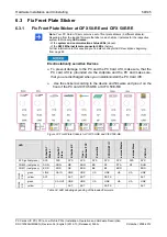
1.  Adhere to the necessary safety precautions for components that are 

vulnerable with electrostatic discharge. 


Electrostatically sensitive Devices 


¾

To prevent damage to the PC and the PC Card cifX, make sure, that the
PC card cifX is grounded via the endplate and the PC and make sure,
that you are discharged when you install/uninstall the PC Card cifX. 


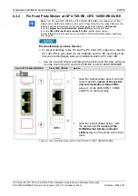
2.   Fix front plate sticker (only for CIFX 50-RE, CIFX 50E-RE, CIFX 70E-

RE or CIFX 100EH-RE\CUBE)). 

¾

  Use the sticker according to the device and firmware and glue it on the 

front of the PC card cifX (see section 

Fix Front Plate Sticker 

on page 

59). 

3.  Set Slot Number (Card ID). 

¾

  For devices with 

Rotary Switch Slot Number (Card ID)

 set the 

Slot 

Number (Card ID)

: (Value 0 or a value from 1 to 9), (see section 

Rotary 

Switch for Slot Number (Card ID) 

on page 91).  

4.  Take safety precautions. 


Lethal Electrical Shock caused by parts with more than 50V! 

¾

  Disconnect the power plug of the PC or of the connecting device. 


¾

  Make sure, that the power supply is off at the PC or at the connecting 

device. 


Device Destruction!


ƒ

  The PC card CIFX 100EH-RE\CUBE may not be installed in standard PCs. The pin 

assignment of the PCI Express bus does not meet the standard [bus spec 3]. By 
consequence malfunction can occur at the PCI express bus.  

ƒ


Install the PC card CIFX 100EH-RE\CUBE exclusively in KEBA KeControl industry PCs 
series CP 3XX (Cube).


5. Open 

cabinet. 

¾

  Open the cabinet of the PC or of the connecting device. 


6.  Install PC Card cifX. 

¾

  Plug the PC card cifX 

PCI

 into a free PCI slot. 

¾

  Plug the PC card cifX 

PCI Express

 or 

Low Profile PCI Express

 into a 

free PCI express slot. 

¾

  Fix the PC card cifX using the hole intended. 

After this: 

7. Close 

cabinet. 

¾

  Close the cabinet of the PC or connecting device. 

Содержание CIFX 100EH

Страница 1: ...50 PCI Express CIFX 50E Low Profile PCI Express CIFX 70E CIFX 100EH Installation Operation and Hardware Description Hilscher Gesellschaft für Systemautomation mbH www hilscher com DOC120204UM36EN Revision 36 English 2012 10 Released Public ...

Страница 2: ...river 14 1 5 1 Hardware PC Cards cifX 14 1 5 2 Reference on Driver and Software 14 1 5 3 Reference on Firmware 15 1 6 Contents of the Product DVD 16 1 6 1 Installation Guide Documentation Overview 16 1 6 2 Device Description Files cifX 16 1 7 Important Changes 17 1 7 1 PROFINET IO Device Firmware Versions 2 1 und 3 4 17 2 SAFETY 18 2 1 General Note 18 2 2 Intended Use 18 2 3 Personnel Qualificatio...

Страница 3: ...FX 50 DP CIFX 50E DP 39 5 1 3 Device Drawings CIFX 50 2DP 41 5 1 4 Device Drawings CIFX 50 CO CIFX 50E CO 42 5 1 5 Device Drawings CIFX 50 DN CIFX 50E DN 44 5 1 6 Device Drawings CIFX 50 2ASM CIFX 50E 2ASM 46 5 1 7 Device Drawings CIFX 50 CC CIFX 50E CC 48 5 1 8 Device Drawings CIFX 50 CP CIFX 50E CP 50 5 2 PC Cards cifX Low Profile PCI Express 52 5 2 1 Device Drawings CIFX 70E RE 52 5 2 2 Device ...

Страница 4: ...Open Modbus TCP 72 8 9 Powerlink Controlled Node Slave 73 8 10 PROFINET IO RT Controller 74 8 11 PROFINET IO RT Device 75 8 12 sercos Master 76 8 13 sercos Slave 77 8 14 VARAN Client Slave 78 8 15 PROFIBUS DP Master 79 8 16 PROFIBUS DP Slave 79 8 17 PROFIBUS MPI Device 80 8 18 CANopen Master 81 8 19 CANopen Slave 82 8 20 DeviceNet Master 83 8 21 DeviceNet Slave 83 8 22 AS Interface Master 84 8 23 ...

Страница 5: ... Express 95 9 10 3 Pin Assignment for PCI Express Bus CIFX 100EH RE CUBE 96 10 TECHNICAL DATA 97 10 1 Technical Data PC Cards cifX 97 10 1 1 CIFX 50 RE 97 10 1 2 CIFX 50 DP 98 10 1 3 CIFX 50 2DP 98 10 1 4 CIFX 50 CO 99 10 1 5 CIFX 50 DN 99 10 1 6 CIFX 50 2ASM 100 10 1 7 CIFX 50 CC 100 10 1 8 CIFX 50 CP 101 10 1 9 CIFX 50E RE 102 10 1 10 CIFX 50E DP 103 10 1 11 CIFX 50E CO 103 10 1 12 CIFX 50E DN 1...

Страница 6: ...ANopen Master 124 10 4 16 CANopen Slave 125 10 4 17 DeviceNet Master 126 10 4 18 DeviceNet Slave 127 10 4 19 AS Interface Master 128 10 4 20 CC Link Slave 129 10 4 21 CompoNet Slave 130 11 ANNEX 131 11 1 Matrix Label 131 11 2 EtherCAT Summary over Vendor ID Conformance test Membership and Network Logo 131 11 2 1 Vendor ID 131 11 2 2 Conformance 132 11 2 3 Certified Product vs Certified Network Int...

Страница 7: ...formation about the Installation of the Software refer to the User Manual Software Installation for PC Cards cifX DOC120207UMXXEN For information about the Wiring of the Protocol Interface refer to the Wiring Instructions DOC120208UMXXEN The devices described in this manual are listed in the sections Devices described in this Manual page 24 The devices are described in detail in the chapters Hardw...

Страница 8: ... Drawings revised and completed drawing for front plate for CIFX 50 2DP added indication for the fieldbus interfaces for 2 channel devices changed to channel 0 and channel 1 as it is displayed in SYCON net Device Assignment Sections Device Drawings CIFX 50 CC CIFX 50E CC and Device Drawings CIFX 50 CP CIFX 50E CP revised current card layout Sections Overview LEDs Fieldbus Systems and AS Interface ...

Страница 9: ...er manual accompanying texts and the documentation were created for the use of the products by qualified experts however errors cannot be ruled out For this reason no guarantee can be made and neither juristic responsibility for erroneous information nor any liability can be assumed Descriptions accompanying texts and documentation included in the user manual do not present a guarantee nor any inf...

Страница 10: ...control systems air traffic or air traffic communication systems in life support systems in systems in which failures in the software could lead to personal injury or injuries leading to death We inform you that the software was not developed for use in dangerous environments requiring fail proof control mechanisms Use of the software in such an environment occurs at your own risk No liability is ...

Страница 11: ...demark of Wind River Systems Inc IntervalZero RTX is a trademark of IntervalZero Adobe Acrobat is a registered trademark of the Adobe Systems Incorporated CANopen is a registered trademark of CAN in AUTOMATION International Users and Manufacturers Group e V CiA Nürnberg CC Link is a registered trademark of Mitsubishi Electric Corporation Tokyo Japan CompoNet DeviceNet und EtherNet IP are trademark...

Страница 12: ...ion of this document under section EtherCAT Summary over Vendor ID Conformance test Membership and Network Logo on page 131 1 3 Licenses If a PC Card cifX is used as a Slave neither for the firmware nor for the configuration software SYCON net a license is required Licenses will be required if the PC Card cifX is used with a firmware with master functionality The master license includes the PC Car...

Страница 13: ...nstruction or 1 instruction 2 instruction Results result Notes Important important note Note note note where to find further information Used Terminology PC Card cifX Communication Interfaces of the cifX family of Hilscher based on the netX technology CIFX 50 RE Example for the product name for a PC card cifX Real Time Ethernet CIFX 50 DP Example for the product name for a PC card cifX PROFIBUS DP...

Страница 14: ...250 100 5 3 1 CIFX 50 DP 1250 410 5 5 1 CIFX 50 2DP 1252 410 2 1 CIFX 50 CO 1250 500 5 5 1 CIFX 50 DN 1250 510 5 5 1 CIFX 50 2ASM 1252 630 2 2 1 CIFX 50 CC 1250 740 2 2 1 CIFX 50 CP 1250 750 2 2 1 CIFX 50E RE 1251 100 5 4 4 CIFX 50E DP 1251 410 6 5 5 CIFX 50E CO 1251 500 5 4 4 CIFX 50E DN 1251 510 5 4 4 CIFX 50E 2ASM 1253 630 5 2 4 CIFX 50E CC 1251 740 4 3 3 CIFX 50E CP 1251 750 4 3 3 CIFX 70E RE ...

Страница 15: ...M NXF sercos Master 2 0 x x from 2 0 14 0 CIFXS3S NXF sercos Slave 3 0 x x from 3 0 13 0 CIFXVRS NXF VARAN Client 1 0 x x from 1 0 3 0 CIFXDPM NXF PROFIBUS DP Master 2 5 x x from 2 3 22 0 CIFX2DPM NXF PROFIBUS DP Master 2 Channels 2 5 x x CIFXDPS NXF PROFIBUS DP Slave 2 4 x x from 2 3 30 0 CIFX2DPS NXF PROFIBUS DP Slave 2 Channels 2 4 x x CIFXMPI NXF PROFIBUS MPI Device 2 4 x x from 2 4 1 2 CIFXCO...

Страница 16: ...d Master device The Real Time Ethernet system Open Modbus TCP does not use device description files The description files for the EtherNet IP Master device is needed when an additional EtherNet IP Master device shall communicate to a Hilscher EtherNet IP Master device via EtherNet IP PC Cards cifX System File Name of the Device Description File EtherCAT Slave Hilscher cifX RE ECS V2 2 x xml or wit...

Страница 17: ...V2 1 x x as well as V3 4 x x The development of the PROFINET IO Device firmware V2 1 x x will not be continued and delivered On the Communication Solutions DVD are both versions V3 4 x x and V2 1 x x available in the directory firmware PROFINET IO Device V3 Directory on the DVD File PROFINET IO Device V2 only on request Firmware Firmware CIFX cifxpns nxf cifxpns nxf Header API Header Firmware PROF...

Страница 18: ...erCAT Slave CIFX 50 DP CIFX 50E DP CIFX 70E DP PROFIBUS DP Master PROFIBUS DP Slave PROFIBUS MPI Device EtherNet IP Scanner Master EtherNet IP Scanner Slave CIFX 50 2DP PROFIBUS DP Master PROFIBUS DP Slave Open Modbus TCP CIFX 50 CO CIFX 50E CO CIFX 70E CO CANopen Master CANopen Slave Powerlink Controlled Node Slave CIFX 50 DN CIFX 50E DN CIFX 70E DN DeviceNet Master DeviceNet Slave PROFINET IO RT...

Страница 19: ...Strictly obey to all safety rules provided by the device s manufacturer in the documentation First disconnect the power plug of the PC or of the connecting device before you open the cabinet Make sure that the power supply is off at the PC or at the connecting device Open the PC cabinet and install or remove the PC Card cifX only after disconnecting power An electrical shock is the result of a cur...

Страница 20: ...oltage Make sure that the limits of the allowed range for the supply voltage are not exceeded A supply voltage above the upper limit can cause severe damage to the PC Card cifX A supply voltage below the lower limit can cause malfunction in the PC Card cifX The allowed range for the supply voltage is defined by the tolerances specified in this manual For the PC cards listed hereafter adhere specif...

Страница 21: ...ge for the PC Cards cifX described in this manual you find in the section Supply Voltage and Signaling Voltage on page 27 There the required and permitted signaling voltage is provided by device type 2 5 3 Electrostatically sensitive Devices This equipment is sensitive to electrostatic discharge which cause internal damage and affect normal operation Therefore adhere to the necessary safety precau...

Страница 22: ...g Meaning USA Indicates a direct hazard with high risk which will have as consequence death or grievous bodily harm if it isn t avoided Indicates a Hazardous Situation Which if not Avoided will Result in Death or Serious Injury Indicates a possible hazard with medium risk which will have as consequence death or grievous bodily harm if it isn t avoided Indicates a Hazardous Situation Which if not A...

Страница 23: ...s the communication of the corresponding Real Time Ethernet or fieldbus system The used Real Time Ethernet systems are The used fieldbus systems are EtherCAT Master EtherCAT Slave EtherNet IP Scanner Master EtherNet IP Adapter Slave Open Modbus TCP Powerlink Controlled Node Slave PROFINET IO RT Controller Master PROFINET IO RT Device Slave sercos Master sercos Slave VARAN Client Slave PROFIBUS DP ...

Страница 24: ...Slave CIFX 50E CP PC Card cifX PCI Express CompoNet Slave CIFX 70E RE PC Card cifX Low Profile PCI Express Real Time Ethernet Master or Slave Low Profile PCIe with RTE CIFX 70E DP PC Card cifX Low Profile PCI Express PROFIBUS DP Master or Slave und PROFIBUS MPI Device Low Profile PCIe with PROFIBUS CIFX 70E CO PC Card cifX Low Profile PCI Express CANopen Master or Slave Low Profile PCIe with CANop...

Страница 25: ... RE CUBE 3 4 1 1 CIFXVRS NXF VARAN Client 1 0 x x CIFXDPM NXF PROFIBUS DP Master 2 3 x x CIFXDPS NXF PROFIBUS DP Slave 2 3 x x CIFX 50 DP CIFX 50E DP CIFX 70E DP 5 5 1 CIFXMPI NXF PROFIBUS MPI Device 2 2 5 0 CIFXCOM NXF CANopen Master 2 3 x x CIFX 50 CO CIFX 50E CO CIFX 70E CO 5 4 1 CIFXCOS NXF CANopen Slave 2 3 x x CIFXDNM NXF DeviceNet Master 2 2 x x CIFX 50 DN CIFX 50E DN CIFX 70E DN 5 4 1 CIFX...

Страница 26: ...CIFXOMB NXF Open Modbus TCP 2 4 x x CIFXPLS NXF POWERLINK Controlled Node 2 1 24 0 CIFXPNM NXF PROFINET IO Controller 2 3 x x CIFXPNS NXF PROFINET IO Device 3 4 x x V3 CIFXS3M NXF sercos Master 2 0 15 0 CIFXS3S NXF sercos Slave 3 0 15 0 CIFX 50 RE CIFX 50E RE CIFX 70E RE CIFX 100EH RE CUBE 1 4 1 1 CIFXVRS NXF VARAN Client 1 0 x x CIFXDPM NXF PROFIBUS DP Master 2 3 x x CIFXDPS NXF PROFIBUS DP Slave...

Страница 27: ...E CUBE exclusively in KEBA KeControl industry PCs series CP 3XX Cube CIFX 100EH RE CUBE 64 PCI Express x4 slot 3 3 V x4 3 Four Lane In the PCI Express x4 slot only lane 0 is used For further details refer to section Pin Assignment for PCI Express Bus CIFX 100EH RE CUBE on page 96 Table 15 Slot for the PC Cards cifX PCI PCIe and Low Profile PCIe 3 2 2 Supply Voltage and Signaling Voltage For the su...

Страница 28: ...processor or higher Windows XP SP3 Windows Vista 32 bit SP2 Windows 7 32 bit or Windows 7 64 bit Administration rights Internet Explorer 5 5 or higher Free disk space min 400 MByte DVD ROM drive RAM min 512 MByte recommended 1024 MByte Graphic resolution min 1024 x 768 pixel Keyboard and Mouse USB optional Note If the project file is saved and opened again or if it is used on another PC the system...

Страница 29: ...mation mbH http www hilscher com 2 The configuration software SYCON net or alternatively the simple Slave configuration tool netX Configuration Tool must be installed or another application program by which the PC Card cifX Slave can be parameterized How to use the Software On how to use the software for the configuration the firmware download and for the diagnosis note the following notice Import...

Страница 30: ...CON net For PC Cards cifX Master or Slave Run the SYCON net Setup and follow to the instructions of the installation wizard 1 3 Installing netX Configuration Tool For PC Cards cifX Slave Start the netX Configuration Tool setup program to install the netX Configuration Tool 2 Preparing Hardware Installation 2 1 Take precautions on Electrostatically sensitive Devices Electrostatically sensitive Devi...

Страница 31: ...oller Important for Hardware Wiring Connect only ports with each other which have different cross over set tings Otherwise a connection bet ween the devices can not be estab lished If the port settings of the PC card cifX PROFINET IO controller are not set to AUTO then Port0 is switched uncrossed and Port1 crossed See corresponding user manual Plug in the connecting cable from the PC card cifX to ...

Страница 32: ... and Configuration 7 1 Downloading Firmware and Configuration Slave If SYCON net was already used on the PC stop the ODMV3 service Therefore select Service Stop from the context menu of the ODMV3 system tray icon Requirements for Operation of the PC Card cifX 29 The ODMV3 system tray icon changes to ODMV3 Service stopped In the netX Configuration Tool select the Firmware protocol Set the PC Card c...

Страница 33: ...e communication to the Master device and to run the diagnosis click on Extended to run the extended diagnosis See Operating Instruction Manual netX Configuration Tool for cifX comX and netJACK Table 18 Steps for the Software and Hardware Installation the Configuration and for the Diagnosis of a PC Card cifX Master and Slave 4 2 Note on Exchange Service Replacement Case For the exchange service rep...

Страница 34: ...t Data Size and Output Data Size and will do further communication to the Slave only if all these values match Therefor the Master reads these parameters from the Slave and compares them with the configuration stored in the Master The parameters Device ID Vendor Code Input Data Size and Output Data Size are part of the SDDML device description file If for the configuration of the sercos Master SDD...

Страница 35: ...olled Node Slave Gateway Stand Alone Slave CIFX RE PLS PROFINET IO RT Controller Master CIFX RE PNM PROFINET IO RT Device Gateway Stand Alone Slave CIFX RE PNS sercos Master Master CIFX RE S3M sercos Slave Gateway Stand Alone Slave CIFX RE S3S CIFX 50 RE CIFX 50E RE CIFX 70E RE CIFX 100EH RE CUBE VARAN Client Slave Gateway Stand Alone Slave CIFX RE VRS PROFIBUS DP Master Master CIFX DP DPM for eac...

Страница 36: ... files are to be saved At existing hardware installation the firmware the driver and the configuration software must be updated according to the versions given in section Reference on Hardware Firmware Software and Driver on page 14 The following graphic gives an overview Figure 1 System Overview cifX to update Firmware Driver and Software Note the specific details for devices with Rotary Switch S...

Страница 37: ... Device Drawing CIFX 50E RE from hardware revision 4 Note Device supports Auto Crossover Function Note also With loaded EtherCAT Master firmware only RJ 45 channel 0 can be used channel 1 is deactivated For Open Modbus TCP with V2 3 4 0 and higher both channels can be used For the SYNC pin assignment of the SYNC Connector refer to section Pin Assignment SYNC Connector X51 on page 93 Device drawing...

Страница 38: ...er Card ID is provided Meaning Rotary Switch Slot Number Card ID The figure shows the rotary switch in position 1 Refer also to section Rotary Switch for Slot Number Card ID page 91 System LED yellow green Communication Status LED 0 red green Communication Status LED 1 red green Designation and meaning depends by protocol Refer also to chapter LED Descriptions page 66 Ethernet Interface Channel 0 ...

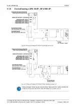
Страница 39: ...ublic Hilscher 2008 2012 5 1 2 Device Drawings CIFX 50 DP CIFX 50E DP Figure 4 Device Drawing CIFX 50 DP hardware revision 5 Figure 5 Device Drawing CIFX 50E DP hardware revision 5 Device drawings of earlier device revisions without rotary switch slot number card ID or with two COM LEDs are included in the user manual for PC cards cifX fieldbus up to manual rev 23 ...

Страница 40: ... 2008 2012 Name Rotary Switch Slot Number Card ID The figure shows the rotary switch in position 1 Refer also to chapter Rotary Switch for Slot Number Card ID page 91 System LED yellow green Communication Status LED COM Refer also to chapter LED Descriptions page 66 PROFIBUS Interface Refer also to chapter PROFIBUS Interface page 88 Table 22 Front Plate CIFX 50 DP or CIFX 50E DP ...

Страница 41: ...12 5 1 3 Device Drawings CIFX 50 2DP Figure 6 Device Drawing CIFX 50 2DP Hardware Revision 2 Name Communication Status LED COM1 red green Communication Status LED COM0 red green System LED yellow green Refer also to chapter LED Descriptions page 66 PROFIBUS Interface Channel 1 PROFIBUS Interface Channel 0 Refer also to chapter PROFIBUS Interface page 88 Table 23 Front Plate CIFX 50 2DP ...

Страница 42: ...lic Hilscher 2008 2012 5 1 4 Device Drawings CIFX 50 CO CIFX 50E CO Figure 7 Device Drawing CIFX 50 CO hardware revision 5 Figure 8 Device Drawing CIFX 50E CO from hardware revision 4 Device drawings of earlier device revisions without rotary switch slot number card ID or with two COM LEDs are included in the user manual for PC cards cifX fieldbus up to manual rev 23 ...

Страница 43: ...0E CO From hardware revision 5 on the Rotary Switch Slot Number Card ID is provided Name Rotary Switch Slot Number Card ID The figure shows the rotary switch in position 1 Refer also to chapter Rotary Switch for Slot Number Card ID page 91 System LED yellow green Communication Status LED CAN red green Refer also to chapter LED Descriptions page 66 CANopen Interface Refer also to chapter CANopen In...

Страница 44: ...leased Public Hilscher 2008 2012 5 1 5 Device Drawings CIFX 50 DN CIFX 50E DN Figure 9 Device Drawing CIFX 50 DN hardware revision 5 Figure 10 Device Drawing CIFX 50E DN from hardware revision 4 Device drawings of earlier device revisions without rotary switch slot number card ID are included in the user manual for PC cards cifX fieldbus up to manual rev 23 ...

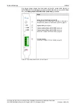
Страница 45: ...Card ID is provided Name Rotary Switch Slot Number Card ID The figure shows the rotary switch in position 1 Refer also to chapter Rotary Switch for Slot Number Card ID page 91 System LED yellow green Communication Status LED MNS red green Refer also to chapter LED Descriptions page 66 DeviceNet Interface refer also to chapter DeviceNet Interface page 89 Note The front plate cutout for the CombiCon...

Страница 46: ...d Public Hilscher 2008 2012 5 1 6 Device Drawings CIFX 50 2ASM CIFX 50E 2ASM Figure 11 Device Drawing CIFX 50 2ASM hardware revision 2 Figure 12 Device Drawing CIFX 50E 2ASM from hardware revision 2 Device drawings of earlier device revisions without rotary switch slot number card ID are included in the user manual for PC cards cifX fieldbus up to manual rev 23 ...

Страница 47: ...Switch Slot Number Card ID is provided Name Rotary Switch Slot Number Card ID The figure shows the rotary switch in position 1 refer also to chapter Rotary Switch for Slot Number Card ID page 91 System LED yellow green Communication Status LED COM0 red green Communication Status LED COM1 red green Refer also to chapter LED Descriptions page 66 AS Interface Interface Channel 0 AS Interface Interfac...

Страница 48: ...CC CIFX 50E CC Figure 13 Device Drawing CIFX 50 CC hardware revision 2 Figure 14 Device Drawing CIFX 50E CC hardware revision 4 Device drawings of earlier device revisions without rotary switch slot number card ID are included in the user manual for PC cards cifX fieldbus up to manual rev 23 Note The front plate cutout for the screw terminal connector is at the PCB side 0 5 mm outside of the stand...

Страница 49: ...FX 50 CC or 3 on CIFX 50E CC the Rotary Switch Slot Number Card ID is provided Name Rotary Switch Slot Number Card ID The figure shows the rotary switch in position 1 refer also to chapter Rotary Switch for Slot Number Card ID page 91 System LED yellow green Communication Status LED L RUN red green Communication Status LED L ERR red green Refer also to chapter LED Descriptions page 66 CC Link Inte...

Страница 50: ...eased Public Hilscher 2008 2012 5 1 8 Device Drawings CIFX 50 CP CIFX 50E CP Figure 15 Device Drawing CIFX 50 CP hardware revision 2 Figure 16 Device Drawing CIFX 50E CP from hardware revision 4 Device drawings of earlier device revisions without rotary switch slot number card ID are included in the user manual for PC cards cifX fieldbus up to manual rev 23 ...

Страница 51: ...CIFX 50 CP or 3 on CIFX 50E CP the Rotary Switch Slot Number Card ID is provided Name Rotary Switch Slot Number Card ID The figure shows the rotary switch in position 1 refer also to chapter Rotary Switch for Slot Number Card ID page 91 System LED yellow green Communication Status LED MS red green Communication Status LED NS red green Refer also to chapter LED Descriptions page 66 CompNet Interfac...

Страница 52: ...ow green Refer also to chapter LED Descriptions page 66 Ethernet Interface Channel 0 Ethernet Interface Channel 1 Refer also to section Ethernet Interface page 86 Note Device supports Auto Crossover Function Note also With loaded EtherCAT Master firmware only RJ 45 channel 0 can be used channel 1 is deactivated For Open Modbus TCP with V2 3 4 0 and higher both channels can be used About Rotary Swi...

Страница 53: ...net Interface Channel 1 Refer also to section Ethernet Interface page 86 Note Device supports Auto Crossover Function Note also With loaded EtherCAT Master firmware only RJ 45 channel 0 can be used channel 1 is deactivated For Open Modbus TCP with V2 3 4 0 and higher both channels can be used About Rotary Switch for Slot Number Card ID refer to section Rotary Switch for Slot Number Card ID on page...

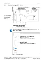
Страница 54: ...rawings CIFX 70E DP Figure 19 Device Drawing CIFX 70E DP Hardware revision 1 About Rotary Switch for Slot Number Card ID refer to section Rotary Switch for Slot Number Card ID on page 91 Meaning Communication Status LED COM red green System LED yellow green Refer also to chapter LED Descriptions page 66 PROFIBUS Interface Refer also to chapter PROFIBUS Interface page 88 Table 31 Front Plate CIFX 7...

Страница 55: ...Drawings CIFX 70E CO Figure 20 Device Drawing CIFX 70E CO Hardware revision 1 About Rotary Switch for Slot Number Card ID refer to section Rotary Switch for Slot Number Card ID on page 91 Meaning Communication Status LED CAN red green System LED yellow green Refer also to chapter LED Descriptions page 66 CANopen Interface Refer also to chapter CANopen Interface page 88 Table 32 Front Plate CIFX 70...

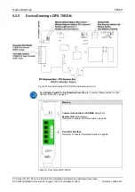
Страница 56: ...awings CIFX 70E DN Figure 21 Device Drawing CIFX 70E DN Hardware revision 1 About Rotary Switch for Slot Number Card ID refer to section Rotary Switch for Slot Number Card ID on page 91 Meaning Communication Status LED MNS red green System LED yellow green Refer also to chapter LED Descriptions page 66 DeviceNet Interface Refer also to chapter DeviceNet Interface page 89 Table 33 Front Plate CIFX ...

Страница 57: ...ard cifX gives information on the manual control elements of your device For the installation uninstalling and replacement of the PC Card cifX check any notes in the overview in chapter Getting Started on page 30 6 1 Safety Messages on Personal Injury Obey to the following safety messages on personal injury when installing uninstalling or replacing the PC Card cifX 6 1 1 Electrical Shock Hazard Le...

Страница 58: ...ding allowed Signaling Voltage Adhere for all PC Cards cifX described in this manual the instruction hereafter Device Destruction All I O signal pins at the PC Card cifX tolerate only the specified signaling voltage Operation the PC card cifX with a signaling voltage other than the specified signaling voltage may lead to severe damage to the PC Card cifX For detailed information on the supply and ...

Страница 59: ...66 Electrostatically sensitive Devices To prevent damage to the PC and the PC Card cifX make sure that the PC card cifX is grounded via the endplate and the PC and make sure that you are discharged when you install uninstall the PC Card cifX Use the sticker according to the device and firmware and glue it on the front of the PC card CIFX 50 RE or CIFX 50E RE Figure 22 Front Plate Stickers for CIFX...

Страница 60: ...his question you find also in chapter LED Descriptions beginning from page 66 Electrostatically sensitive Devices To prevent damage to the PC and the PC Card cifX make sure that the PC card cifX is grounded via the endplate and the PC and make sure that you are discharged when you install uninstall the PC Card cifX Use the two part sticker according to the device and firmware and glue it on the fr...

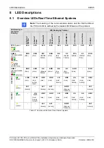
Страница 61: ... 100EH RE CUBE LED EtherCAT Master EtherCAT Slave EtherNet IP Open Modbus TCP Powerlink PROFINET IO sercos Master sercos Slave VARAN SYS yellow green SYS SYS SYS SYS SYS SYS SYS SYS SYS COM 0 red green RUN RUN MS RUN BS SF STA S3 RUN COM 1 red green ERR ERR NS ERR BE BF ERR ERR green LINK L A IN LINK LINK L A LINK L A L A LINK RJ45 Ch0 yellow ACT ACT ACT RX TX ACT green L A OUT LINK LINK L A LINK ...

Страница 62: ...D For devices with Rotary Switch Slot Number Card ID set the Slot Number Card ID Value 0 or a value from 1 to 9 see section Rotary Switch for Slot Number Card ID on page 91 4 Take safety precautions Lethal Electrical Shock caused by parts with more than 50V Disconnect the power plug of the PC or of the connecting device Make sure that the power supply is off at the PC or at the connecting device D...

Страница 63: ...ing device to the power supply and switch it on Connect the PC or the connecting device to the power supply Switch on the PC or the connecting device 6 5 Uninstalling the PC Card cifX PCI PCIe Low Profile PCIe 1 Take safety precautions Lethal Electrical Shock caused by parts with more than 50V Disconnect the power plug of the PC or of the connecting device Make sure that the power supply is off at...

Страница 64: ... from page 66 Cable Check that the pin assignment of the cable is correct This means the cable by which you connect the PC card cifX to the PC card Master or Slave Configuration Check the configuration in the Master device and the Slave device The configuration has to match Diagnostic using the Configuration Software SYCON net With the menu Online Diagnosis the diagnostic information of the device...

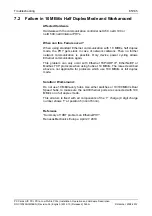
Страница 65: ... further network communication is possible Only device power cycling allows Ethernet communication again This problem can only occur with Ethernet TCP UDP IP EtherNet IP or Modbus TCP protocols when using hubs at 10 MBit s The issue described above is not applicable for protocols which use 100 MBit s or full duplex mode Solution Workaround Do not use 10 MBit s only hubs Use either switches or 10 1...

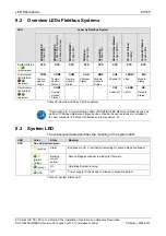
Страница 66: ...Status yellow green RUN RUN MS RUN BS SF STA S3 RUN COM 0 Communication Status red green orange red green simultaneously Run Run Module Status Run Bus Status System Failure Status Status Error Run ERR ERR NS ERR BE BF ERR ERR COM 1 Communication Status red green Error Error Network Status Error Bus Error Bus Failure Error Error LINK L A IN LINK LINK L A LINK L A L A LINK green Link Link Activity I...

Страница 67: ...s CANopen Status Module Network Status Channel 0 L Run Module Status COM1 CH1 L ERR NS Communica tion Status 1 red green Commu nication Status 1 Channel 1 L Error Network Status Table 38 Overview LEDs by Fieldbus System Descriptions for 2 Communication LEDs of PROFIBUS DP Master and Slave devices as well as of CANopen Master and Slave devices of earlier device revisions are included in the user ma...

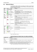
Страница 68: ...ng COM 1 red On Master has detected a communication error The error is indicated in the DPM LED green green On A link is established LINK RJ45 Ch0 off Off No link established LED yellow ACT RJ45 Ch0 yellow Flashing The device sends receives Ethernet frames Table 40 LEDs EtherCAT Master LED State Definition for EtherCAT Master for the RUN and ERR LEDs Indicator state Definition On The indicator is ...

Страница 69: ...vice application has changed the EtherCAT state autonomously Possible reason 1 A host watchdog timeout has occurred Possible reason 2 Synchronization Error device enters Safe Operational automatically ERR Name in the device drawing COM 1 red Double Flash Application Watchdog Timeout An application watchdog timeout has occurred Possible reason Sync Manager Watchdog timeout LED green green On A link...

Страница 70: ...ff No power If no power is supplied to the device the module status indicator shall be steady off Duo LED red green green On Connected If the device has at least one established connection even to the Message Router the network status indicator shall be steady green green Flashing No connections If the device has no established connections but has obtained an IP address the network status indicato...

Страница 71: ...f No power If no power is supplied to the device the module status indicator shall be steady off Duo LED red green green On Connected If the device has at least one established connection even to the Message Router the network status indicator shall be steady green green Flashing No connections If the device has no established connections but has obtained an IP address the network status indicator...

Страница 72: ... Ready not configured yet OMB task is ready and not configured yet green Flashing cyclic with 5Hz Waiting for Communication OMB task is configured RUN Name in the device drawing COM 0 green On Connected OMB task has communication at least one TCP connection is established Duo LED red green off Off No communication error red Flashing cyclic with 2Hz On Off Ratio 25 System error ERR Name in the devi...

Страница 73: ...ernet LED yellow RJ45 Ch0 Ch1 This LED is not used Table 47 LEDs Powerlink Controlled Node Slave LED State Definition for Powerlink Controlled Node Slave for the BS BE LEDs Indicator state Definition On The indicator is constantly on Off The indicator is constantly off Blinking The indicator turns on and off with a frequency of approximately 2 5 Hz on for approximately 200 ms followed by off for 2...

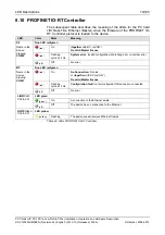
Страница 74: ...red ON No valid Master license red Flashing cyclic at 2 Hz System error Invalid configuration Watchdog error or internal error SF Name in the device drawing COM 0 off Off No error Duo LED red green red On No Connection No Link or together with SF red ON No valid Master license red Flashing cyclic at 2 Hz Configuration fault not all configured IO Devices are connected BF Name in the device drawing ...

Страница 75: ... Watchdog timeout channel generic or extended diagnosis present system error red Flashing cyclic at 2 Hz for 3 sec DCP signal service is initiated via the bus SF Name in the device drawing COM 0 off Off No error Duo LED red green red On No configuration or low speed physical link or no physical link red Flashing cyclic at 2 Hz No data exchange BF Name in the device drawing COM 1 off Off No error L...

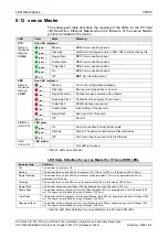
Страница 76: ...o error LED green green On Link A connection to the Ethernet exists green Flashing Activity The device sends receives Ethernet frames L A RJ45 Ch0 Ch1 off Off The device has no connection to the Ethernet LED yellow RJ45 Ch0 Ch1 This LED is not used Table 51 LEDs sercos Master LED State Definition for sercos Master for STA and ERR LEDs Indicator state Definition Off The indicator is constantly off ...

Страница 77: ...ms red On SIII C1D Error detected according to sercos third generation Cass 1 Diagnosis orange On CP0 CP3 Communication phase 0 to Communication phase 3 orange Flashing 4 Hz Identification Bit 15 in the Slave device control that indicates remote address allocation or configuration errors between Master and Slaves for details refer to sercos Slave Protocol API pdf on the product DVD STA Name in the...

Страница 78: ... On Configured and communication is active Duo LED red green off Off Configured red Blinking Not configured ERR Name in the device drawing COM 1 red On Communication error occurred LED green green On A connection to the Ethernet exists LINK RJ45 Ch0 Ch1 off Off The device has no connection to the Ethernet LED yellow ACT RJ45 Ch0 Ch1 yellow Flashing The device sends receives Ethernet frames Table 5...

Страница 79: ...us error has occured Redundant Mode The active Master was not found Table 57 LEDs PROFIBUS DP Master 1 Communication LED current Hardware Revision Note For 2 Channel Devices per channel works 1 communication LED Descriptions for 2 Communication LEDs of earlier device revisions are included in the user manual for PC cards cifX fieldbus up to manual rev 23 8 16 PROFIBUS DP Slave The subsequent table...

Страница 80: ...atus The device currently holds the PROFIBUS token and is able to transfer telegrams of data green Blinking regularly 5 Hz Status The device is configured to be a part of the PROFIBUS ring but it must share the PROFIBUS token with other PROFIBUS Master devices present on the PROFIBUS ring green Blinking regularly 0 5 Hz Status Automatic baudrate detection is running red On Error Communication erro...

Страница 81: ...flash Error Control Event A guard event NMT Slave or NMT master or a heartbeat event Heartbeat consumer has occurred CAN red On Bus Off The CAN controller is bus off Table 60 LEDs CANopen Master 1 Communication LED current Hardware Revision LED State Definition for CANopen Master for the CAN LED Indicator state Definition On The indicator is constantly on Off The indicator is constantly off Flicke...

Страница 82: ... or exceeded the warning level too many error frames red Double flash Error Control Event A guard event NMT Slave or NMT master or a heartbeat event Heartbeat consumer has occurred CAN red On Bus Off The CAN controller is bus off Table 62 LEDs CANopen Slave 1 Communication LED current Hardware Revision LED State Definition for CANopen Slave for the CAN LED Indicator state Definition On The indicat...

Страница 83: ... Flashing Connection timeout MNS off Off Device is not powered Device is not on line The device has not completed the Dup_MAC_ID test yet The device may not be powered Table 64 LEDs DeviceNet Master 8 21 DeviceNet Slave The subsequent table describes the meaning of the LEDs for the PC Card cifX DeviceNet Slave when the firmware of the DeviceNet Slave protocol is loaded to the device LED Color Stat...

Страница 84: ...reen Flashing fast The Communication is stopped red green Flashing Configuration mode active red Flashing AS Interface power fail red On Heavy System error or hardware failure CH1 off Off No configuration found for this channel Table 66 LEDs AS Interface Master 8 23 CC Link Slave The subsequent table describes the meaning of the LEDs for the PC Card cifX CC Link Slave when the firmware of the CC L...

Страница 85: ...d On Unrecoverable Fault If the device has detected a non recoverable major fault the MS LED shall be steady red It may be necessary to replace the Slave device MS red green Flashing Device Self Test While the device is performing its self test the MS LED shall be flashing green red Duo LED red green off Off No power Speed Detection If no power is supplied to the device or the network data rate is...

Страница 86: ... be switched The following figure shows the RJ45 standard pin assignment Figure 25 Ethernet Pin Assignment at the RJ45 Socket for cifX or AIFX Pin Signal Meaning 1 TX Transmit Data 2 TX Transmit Data 3 RX Receive Data 4 Term 1 5 Term 1 Connected to each other and terminated to PE through RC circuit 6 RX Receive Data 7 Term 2 8 Term 2 Connected to each other and terminated to PE through RC circuit ...

Страница 87: ...T forbidden only allowed between EtherCAT Master and first EtherCAT Slave 100 MBit s Full Duplex EtherNet IP allowed allowed 10 MBit s 100 MBit s Full or Half Duplex Auto Negotiation Open Modbus TCP allowed allowed 10 MBit s 100 MBit s Full or Half Duplex Auto Negotiation POWELINK allowed forbidden PROFINET IO RT forbidden Only allowed if the switch supports Priority Tagging and LLDP 100 MBit s Fu...

Страница 88: ...emale connector Signal Meaning 3 RxD TxD P Receive Send Data P respectively connection B plug 5 DGND Reference potential 6 VP Positive supply voltage 8 RxD TxD N Receive Send Data N respectively connection A plug Table 72 PROFIBUS Interface X400 9 3 CANopen Interface Isolated ISO 11898 interface Figure 27 CANopen Interface DSub male connector 9 pin X400 Connection with DSub male connector Signal D...

Страница 89: ...nce potential DeviceNet supply voltage 2 CAN_L Blue CAN Low Signal 3 Drain Shield 4 CAN_H White CAN High Signal 5 V Red 24 V DeviceNet supply voltage Table 74 DeviceNet Interface X360 9 5 AS Interface Interface The AS Interface Master conforms to Complete Specification 2 11 Annex B Version 2 0 the profile M3 Full Extended Master AS Interface interface according to IEC 364 4 41 Figure 29 AS Interfa...

Страница 90: ...ng 1 DA Data A 2 DB Data B 3 DG Data Ground 4 SLD Shield 5 FG Field Ground Table 76 CC Link Interface 9 7 CompoNet Interface Drawing of the CompoNet Interface The following drawing shows the CompoNet interface Open Jack connector 4 pin according to CompoNet Specification Figure 31 CompoNet Interface Open Jack Connector 4 pin Connection with Open Jack connector pin Signal Color Description Terminal...

Страница 91: ... and serial number Example Rotary Switch Slot Number Card ID Switch Position 0 1 9 corresponds to the Slot Number Card ID 1 9 Example Rotary Switch Slot Number Card ID Switch Position 1 Table 78 Rotary Switch for Slot Number Card ID S1 9 8 1 Set Slot Number Card ID If the Slot Number Card ID shall not be used set the value 0 Or If the Slot Number Card ID shall be used Set a value from 1 to 9 For f...

Страница 92: ...008 2012 9 8 3 Rotary Switch Slot Number PC Cards cifX Low Profile The Table 79 below shows the Rotary Switch Slot Number Card ID of the PC Cards cifX Low Profile PCI Express in switch position 0 and 1 Description Rotary Switch Slot Number Card ID Switch Position 0 Rotary Switch Slot Number Card ID Switch Position 1 Table 79 Rotary Switch Slot Number Card ID PC Cards cifX Low Profile PCI Express ...

Страница 93: ...t SYNC Connector J3 CIFX 100EH Only for CIFX 100EH RE CUBE Pin Signal 1 IO_SYNC0 2 Jumper set SYNC signal is transferred to the PCI Express Bus Pin B24 Jumper not set static high 3 3 V with pull up 3 IO_SYNC1 Table 81 Pin Assignment for SYNC Connector J3 Note If the jumper is set on Pin1 Pin2 then the IO_SYNC0 signal will be transferred to the PCI Express Bus X2 pin B24 Or If the jumper is set on ...

Страница 94: ...058 SYNC connector J3 for CIFX 100EH RE CUBE Male Connector with jumper 3 pin pitch spacing 2 54 mm Max Cable Length Recommendation Max 50 mm Note Take EMC into consideration for the cable laying Table 82 SYNC Connector SYNC Signal Connector Max Cable Length 9 9 4 Items on Firmware The firmware determines the input signal or output signal The following table shows the meaning of the SYNC signals f...

Страница 95: ...SM CIFX 50 CC CIFX 50 CP 5 5 2 5 5 2 2 2 PCI 124 yes bus spec 1 CIFX 50E RE CIFX 50E DP CIFX 50E CO CIFX 50E DN CIFX 50E 2ASM CIFX 50E CC CIFX 50E CP 5 6 5 5 5 4 4 PCI Express 36 yes bus spec 2 Rev 2 0 bus spec 3 CIFX 70E RE CIFX 70E DP CIFX 70E CO CIFX 70E DN 1 1 1 1 CIFX 100EH RE CUBE 4 PCI Express 64 no Pin Assignment for PCI Express Bus CIFX 100EH RE CUBE 96 bus spec 2 Rev 2 0 bus spec 3 Table...

Страница 96: ... B15 PCIe_TN Transmitter Lane differential pair A15 GND Ground B16 GND Ground A16 PCIe_RP B17 PRSNT2 Hot Plug presence detect A17 PCIe_RN Receiver Lane differential pair B18 GND Ground A18 GND Ground B19 n u not used A19 n u not used B20 n u not used A20 n u not used B21 n u not used A21 n u not used B22 n u not used A22 n u not used B23 GND Ground A23 n u not used B24 IO_SYNC0 IO_SYNC1 3 3V 5 Rea...

Страница 97: ...ink Controlled Node Slave PROFINET IO Controller Master PROFINET IO Device Slave sercos Master sercos Slave VARAN Client Slave Ethernet Frame Types Ethernet II Processor netX 500 LEDs SYS COM 0 COM 1 2x Link 2x Activity refer also to chapter LED Descriptions page 66 Rotary Switch Slot Number Card ID To set the Slot Number Card ID Configuration Software SYCON net Master and Slave or netX Configurat...

Страница 98: ... x 86 x 18 5 mm W 86 mm as with Rotary Switch Slot Number Card ID Operating Temperature 20 C 55 C Environment The device must be used in a pollution degree 2 environment UL Certification The device is UL 508 certified UL File No E221530 Table 88 Technical Data CIFX 50 DP 10 1 3 CIFX 50 2DP Item CIFX 50 2DP System Interface Bus Type PCI according to bus spec 1 refer to section Overview on the Pin A...

Страница 99: ...vironment The device must be used in a pollution degree 2 environment UL Certification The device is UL 508 certified UL File No E221530 Table 90 Technical Data CIFX 50 CO 10 1 5 CIFX 50 DN Item CIFX 50 DN System Interface Bus Type PCI according to bus spec 1 refer to section Overview on the Pin Assignment at the Bus page 95 33 MHz 32 Bit width for the data access to the Dual Port Memory DPM or IO...

Страница 100: ...C Environment The device must be used in a pollution degree 2 environment UL Certification The device is UL 508 certified UL File No E221530 Table 92 Technical Data CIFX 50 2ASM 10 1 7 CIFX 50 CC Item CIFX 50 CC System Interface Bus Type PCI according to bus spec 1 refer to section Overview on the Pin Assignment at the Bus page 95 33 MHz 32 Bit width for the data access to the Dual Port Memory DPM...

Страница 101: ...terface Communication Determined by the loaded firmware Protocols CompoNet Slave Processor netX 100 LEDs SYS MS NS refer also to chapter LED Descriptions page 66 Rotary Switch Slot Number Card ID To set the Slot Number Card ID Configuration Software netX Configuration Tool or SYCON net CompoNet Interface Open Jack connector 4 pin according to CompoNet Specification refer also to chapter CompoNet I...

Страница 102: ...trolled Node Slave PROFINET IO Controller Master PROFINET IO Device Slave sercos Master sercos Slave VARAN Client Slave Ethernet Frame Types Ethernet II Processor netX 500 LEDs SYS COM 0 COM 1 2x Link 2x Activity refer also to chapter LED Descriptions page 66 Rotary Switch Slot Number Card ID To set the Slot Number Card ID Configuration Software SYCON net Master and Slave or netX Configuration Too...

Страница 103: ... ID Operating Temperature 0 C 55 C Environment The device must be used in a pollution degree 2 environment UL Certification The device is UL 508 certified UL File No E221530 Table 96 Technical Data CIFX 50E DP 10 1 11 CIFX 50E CO Item CIFX 50E CO System Interface Bus Type PCI Express One Lane Port according to bus spec 2 Rev 2 0 and bus spec 3 refer to section Overview on the Pin Assignment at the...

Страница 104: ... x 86 x 18 5 mm W 86 mm as with Rotary Switch Slot Number Card ID Operating Temperature 0 C 55 C Environment The device must be used in a pollution degree 2 environment UL Certification The device is UL 508 certified UL File No E221530 Table 98 Technical Data CIFX 50E DN 10 1 13 CIFX 50E 2ASM Item CIFX 5E0 2ASM System Interface Bus Type PCI Express One Lane Port according to bus spec 2 Rev 2 0 and...

Страница 105: ...ting Temperature 0 C 55 C Environment The device must be used in a pollution degree 2 environment UL Certification The device is UL 508 certified UL File No E221530 Table 100 Technical Data CIFX 50E CC 10 1 15 CIFX 50E CP Item CIFX 50E CP System Interface Bus Type PCI Express One Lane Port according to bus spec 2 according Rev 1 0a and bus spec 3 refer to section Overview on the Pin Assignment at ...

Страница 106: ...us TCP Powerlink Controlled Node Slave PROFINET IO Controller Master PROFINET IO Device Slave sercos Master sercos Slave VARAN Client Slave Ethernet Frame Types Ethernet II Processor netX 100 LEDs SYS COM 0 COM 1 2x Link 2x Activity refer also to chapter LED Descriptions page 66 Rotary Switch Slot Number Card ID To set the Slot Number Card ID Configuration Software SYCON net Master and Slave or ne...

Страница 107: ... EtherCAT Slave EtherNet IP Scanner Master EtherNet IP Adapter Slave Open Modbus TCP Powerlink Controlled Node Slave PROFINET IO Controller Master PROFINET IO Device Slave sercos Master sercos Slave VARAN Client Slave Ethernet Frame Types Ethernet II Processor netX 100 LEDs SYS COM 0 COM 1 2x Link 2x Activity refer also to chapter LED Descriptions page 66 Rotary Switch Slot Number Card ID To set t...

Страница 108: ... mm Operating Temperature 0 C 65 C Environment The device must be used in a pollution degree 2 environment UL Certification The device is UL 508 certified UL File No E221530 Table 104 Technical Data CIFX 70E DP 10 1 19 CIFX 70E CO Item CIFX 70E CO System Interface Bus Type PCI Express One Lane Port according to bus spec 2 Rev 2 0 and bus spec 3 refer to section Overview on the Pin Assignment at th...

Страница 109: ...nd DeviceNet interface Communication Determined by the loaded firmware Protocols DeviceNet Master DeviceNet Slave Processor netX 100 LEDs SYS MNS refer also to chapter LED Descriptions page 66 Rotary Switch Slot Number Card ID To set the Slot Number Card ID Configuration Software SYCON net Master and Slave or netX Configuration Tool only Slave DeviceNet Interface CombiCon male Connector 5 pin Isol...

Страница 110: ...llowing table you can see which PCI bus commands are supported by the Hilscher PC cards cifX PCI Compact PCI Mini PCI and PCI 104 C BE3 C BE2 C BE1 C BE0 Command Type supported 0 0 0 0 Interrupt Acknowledge no 0 0 0 1 Special Cycle no 0 0 1 0 I O Read 9 0 0 1 1 I O Write 9 0 1 0 0 Reserved no 0 1 0 1 Reserved no 0 1 1 0 Memory Read 9 0 1 1 1 Memory Write 9 1 0 0 0 Reserved no 1 0 0 1 Reserved no 1...

Страница 111: ...aximum 1500 bytes Functions Get OD List Get object description Get entry description Emergency Slave diagnostics Bus Scan Supported Redundancy Supported but not at the same time with Distributed Clocks Distributed Clocks Supported but not at the same time with Redundancy Topology Line or ring Baud rate 100 MBit s Data transport layer Ethernet II IEEE 802 3 Configuration File ethercat xml or config...

Страница 112: ...ns Emergency FMMUs 3 netX 100 netX 500 SYNC Manager 4 netX 100 500 Distributed Clocks DC Supported 32 Bit Baud rate 100 MBit s Data transport layer Ethernet II IEEE 802 3 Limitation LRW is not supported Reference to firmware stack version V2 5 x x Table 110 Technical Data EtherCAT Slave Protocol Note The loadable firmware supports for the number of cyclic input data and for cyclic output data in t...

Страница 113: ...mber of connections and used number of input and output data Maximum number of unscheduled data 1400 bytes per telegram UCMM Class 3 Supported Explicit Messages Client and Server Services Get_Attribute_Single All Set_Attribute_Single All Predefined standard objects Identity Object Message Route Object Assembly Object Connection Manager Ethernet Link Object TCP IP Object Maximal number of user spec...

Страница 114: ...M Supported Maximum number of user specific objects 20 Maximum number of connections 8 explicit and implicit connections Predefined standard objects Identity Object Message Route Object Assembly Object Connection Manager Ethernet Link Object TCP IP Object Topology Tree Line Ring DLR Device Level Ring Beacon based Ring Node ACD Address Conflict Detection Supported DHCP Supported BOOTP Supported Bau...

Страница 115: ...Client Mode Client using the Command Table The data is stored in the I O process data image Client using the packet API The I O process data image is not used Server using the packet API The I O process data image is not used I O Mode Server Mode Server only The data is stored in the I O process data image Baud rates 10 and 100 MBit s Data transport layer Ethernet II IEEE 802 3 Reference to firmwa...

Страница 116: ...d configuration Protocol CL RPC Connectionless Remote Procedure Call Context management by CL RPC Supported Minimum cycle time 1 ms Different IO Devices can be configured with different cycle times Functions Fast Startup of PROFINET IO Devices supported Baud rate 100 MBit s Full Duplex mode Data transport layer Ethernet II IEEE 802 3 Configuration file Maximum 1 MByte Limitations RT over UDP not s...

Страница 117: ... IP ARP ICMP Ping Topology recognition LLDP SNMP V1 MIB2 physical device VLAN and priority tagging yes Context Management by CL RPC Supported Identification Maintenance Read and write of I M1 4 Minimum cycle time 1 ms for RTC1 and RTC2 250 µs for RTC3 Baud rate 100 MBit s Data transport layer Ethernet II IEEE 802 3 Limitations RT over UDP not supported Multicast communication not supported Only on...

Страница 118: ...ces 511 Minimum cycle time 250 µs Acyclic communication Service channel Read Write Commands Functions Bus Scan Communication phases NRT CP0 CP1 CP2 CP3 CP4 Topology Line and double ring Redundancy supported Baud rate 100 MBit s full duplex Data transport layer Ethernet II IEEE 802 3 Auto crossover supported Supported sercos version Communication Specification Version 1 1 1 1 1 2 Limitations NRT ch...

Страница 119: ...cation phases NRT CP0 CP1 CP2 CP3 CP4 Acyclic Communication Service Channel Read Write Standard Commands Baud rate 100 MBit s Data transport layer Ethernet II IEEE 802 3 Supported sercos version sercos in the third generation Communication Specification Version 1 1 2 Supported sercos Communication Profiles SCP_FixCFG Version 1 1 1 SCP_VarCFG Version 1 1 1 SCP_VarCFG Version 1 1 3 Supported User SC...

Страница 120: ...data 128 bytes Memory Area Read Memory Area 1 Write Memory Area 1 Functions Memory Read Memory Write Integrated 2 port splitter for daisy chain topology Supported Baud rate 100 MBit s Data transport layer Ethernet II IEEE 802 3 VARAN protocol version 1 1 1 0 Limitations Integrated EMAC for IP data exchange with client application not supported SPI single commands optional feature not supported Mem...

Страница 121: ...ve standard parameters Max 237 bytes slave application specific parameters Acyclic communication DP V1 Class 1 Read Write DP V1 Class 1 Alarm DP V1 Class 2 Initiate Read Write Datatransport Abort Maximum number of acyclic read write 240 bytes slave Functions Configuration in Run CiR Timestamp Master functionality Redundancy supported requires host application program support Baud rate 9 6 kBits s ...

Страница 122: ...Parameter data 237 bytes application specific parameters Acyclic communication DP V1 Class 1 Read Write DP V1 Class 1 Alarm DP V1 Class 2 Read Write Data Transport Baud rate 9 6 kBits s 19 2 kBits s 31 25 kBits s 45 45 kBits s 93 75 kBits s 187 5 kBits s 500 kBits s 1 5 MBits s 3 MBits s 6 MBits s 12 MBit s Auto baudrate detection is supported Data transport layer PROFIBUS FDL Limitations SSCY1S S...

Страница 123: ...ytes Functions MPI Read Write DB data block M marker Q output C Counter T Timer MPI Read I Input Data type bit to access to DB data block M marker Q output and I Input read only MPI Connect automatically when first read write function is used MPI Disconnect MPI Disconnect All MPI Get OP Status MPI transparent expert use only Baud rate Fixed values ranging from 9 6 kBits s to 12 MBit s Auto detecti...

Страница 124: ...ansfer synchronized remotely requested and event driven change of date Acyclic communication SDO Upload Download max 512 bytes per request Functions Emergency message consumer and producer Node guarding life guarding heartbeat PDO mapping NMT Master SYNC protocol producer Simple boot up process reading object 1000H for identification Baud rates 10 kBits s 20 kBits s 50 kBits s 100 kBits s 125 kBit...

Страница 125: ...sted and event driven change of date event timer On request of the host application program via packet Acyclic communication SDO upload download Emergency message producer Timestamp producer consumer Functions Node guarding life guarding heartbeat PDO mapping NMT Slave SYNC protocol consumer Baud rates 10 kBits s 20 kBits s 50 kBits s 100 kBits s 125 kBits s 250 kBits s 500 kBits s 800 kBits s 1 M...

Страница 126: ...es connection Maximum Configuration data 1000 bytes slave Acyclic communication Explicit connection All service codes are supported Connections Bit Strobe Change of State Cyclic Poll Explicit Peer to Peer Messaging Function Quick Connect Fragmentation Explicit and I O UCMM Supported Objects Identity Object Class Code 0x01 Message Router Object Class Code 0x02 DeviceNet Object Class Code 0x03 Conne...

Страница 127: ...of cyclic output data 255 bytes Acyclic communication Get_Attribute_Single All Max 240 bytes per request Set_Attribute_Single All Max 240 bytes per request Connections Poll Change of state Cyclic Bit strobe Explicit messaging Supported Fragmentation Explicit and I O UCMM Not supported Baud rates 125 kBits s 250 kBit s 500 kBit s Auto baudrate detection is not supported Data transport layer CAN fra...

Страница 128: ...lic input data Max 4 Bit digital data Max 4 channel with up to 16 bit analog data The maximum number depends on the used slave profiles Maximum number of cyclic output data Max 4 Bit digital data Max 4 channel with up to 16 bit analog data The maximum number depends on the used slave profiles Parameterization data 4 bit per standard slave 3 bit per extended slave Maximum number of acyclic read wri...

Страница 129: ...ension cycles 1 2 4 8 Baud rates 156 kBit s 625 kBit s 2500 kBit s 5 MBit s 10 MBit s Limitation Intelligent Device Station not supported Firmware works according to CC Link Version 1 11 Station Types Remote I O station Remote device station up to 4 occupied stations Maximum input data 48 bytes Maximum output data 48 bytes Input data remote I O station 4 bytes RY Output data remote I O station 4 b...

Страница 130: ...ts Bits Word 8 16 32 256 Points Bits Acyclic communication Explicit messaging A_EVENT Max number of user specific objects 64 Predefined standard objects Identity Object Connection Object CompoNet Link Object Frametypes supported OUT TRG CN IN A_EVENT B_EVENT BEACON Fragmentation of Explicit Messages Supported Node Address 0 63 for Word IN Word MIX Word OUT 0 127 for Bit IN Bit MIX Bit OUT MAC ID 0...

Страница 131: ...2 EtherCAT Summary over Vendor ID Conformance test Membership and Network Logo 11 2 1 Vendor ID The communication interface product is shipped with Hilscher s secondary vendor ID which has to be replaced by the Vendor ID of the company shipping end products with the integrated communication interface End Users or Integrators may use the communication interface product without further modification ...

Страница 132: ...AT conformance requirements For example certain communication parameters are set by a software stack in which case the actual software implementation in the device application determines whether or not the network interface can pass the EtherCAT conformance test In such cases conformance test of the end product must be passed to ensure that the implementation does not affect network compliance Gen...

Страница 133: ...ctronic equipment may not be disposed of with household waste As a consumer you are legally obliged to dispose all Waste electronic equipment professionally as to the public collection 11 4 References References referring to the safety issues are listed separately in section References Safety on page 22 References referring to the Standard Bus Specifications for PCI and PCI Express are listed sepa...

Страница 134: ...e Drawing CIFX 50 CC hardware revision 2 48 Figure 14 Device Drawing CIFX 50E CC hardware revision 4 48 Figure 15 Device Drawing CIFX 50 CP hardware revision 2 50 Figure 16 Device Drawing CIFX 50E CP from hardware revision 4 50 Figure 17 Device Drawing CIFX 70E RE Hardware revision 1 52 Figure 18 Device Drawing CIFX 100EH RE CUBE 53 Figure 19 Device Drawing CIFX 70E DP Hardware revision 1 54 Figur...

Страница 135: ...ation of the Master Device 34 Table 20 Device Names in SYCON net by Communication Protocol 35 Table 21 Front Plate for CIFX 50 RE or CIFX 50E RE 38 Table 22 Front Plate CIFX 50 DP or CIFX 50E DP 40 Table 23 Front Plate CIFX 50 2DP 41 Table 24 Front Plate for CIFX 50 CO or CIFX 50E CO 43 Table 25 Front Plate CIFX 50 DN or CIFX 50E DN 45 Table 26 Front Plate CIFX 50 2ASM 47 Table 27 Front Plate CIFX...

Страница 136: ...se of Hubs and Switches 87 Table 72 PROFIBUS Interface X400 88 Table 73 CANopen Interface X400 88 Table 74 DeviceNet Interface X360 89 Table 75 AS Interface Interface 89 Table 76 CC Link Interface 90 Table 77 CompoNet Interface 90 Table 78 Rotary Switch for Slot Number Card ID S1 91 Table 79 Rotary Switch Slot Number Card ID PC Cards cifX Low Profile PCI Express 92 Table 80 Pin Assignment for SYNC...

Страница 137: ...ocol 115 Table 114 Technical Data POWERLINK Controlled Node Slave Protocol 115 Table 115 Technical Data PROFINET IO RT Controller 117 Table 116 Technical Data PROFINET IO RT IRT Device Protocol 117 Table 117 Technical Data sercos Master Protocol 118 Table 118 Technical Data sercos Slave Protocol 119 Table 119 Technical Data VARAN Client Protocol 120 Table 120 Technical Data PROFIBUS DP Master Prot...

Страница 138: ... if the data lines have been exchanged vice versa Auto Negotiation Auto Negotiation is a feature of an interface An interface with Auto Negotiation will automatically determine a set of correct communication parameters Baud rate Data transmission speed of a communication channel or interface Boot loader Program loading the firmware into the memory of a device in order to be executed cifX Communica...

Страница 139: ...ory EDS Electronic Data Sheet EDS file A special kind of Device Description File used for example by EtherNet IP EtherCAT A communication system for industrial Ethernet designed and developed by Beckhoff Automation GmbH Ethernet A networking technology used both for office and industrial communication via electrical or optical connections It has been developed and specified by the Intel DEC and XE...

Страница 140: ...s Modbus function codes are elements of Modbus request reply telegrams GSD Generic Station Description Device description file GSD file A special kind of Device Description File used by PROFIBUS GSD Generic Station Description GSDML Generic Station Description Markup Language XML based device description file GSDML file A special kind of XML based Device Description File used by PROFINET Half dupl...

Страница 141: ...s Discrete Inputs inputs FC 2 Read coils outputs FC 1 5 15 Write and Read back Input register input data FC 4 Read Holding register output data FC 3 6 16 23 Write and Read back It should be noted however that depending on the device manufacturer and device type the data area in the device may be present or not and two data areas can be combined into one data region For example discrete inputs and ...

Страница 142: ...Powerlink PROFINET IO RT sercos VARAN PROFIBUS DP PROFIBUS MPI CANopen DeviceNet AS Interface CompoNet CC Link as Communication Interface netX with PCI Bus PCI CIFX50 PCI Express CIFX 50E Low Profile PCI Express CIFX 70E CIFX 100EH RE CUBE Compact PCI CIFX80 Mini PCI CIFX90 Mini PCI Express CIFX 90E PCI 104 CIFX 104C and as Communication Interface netX with ISA Bus PC 104 CIFX 104 only Real Time E...

Страница 143: ...tiple registers sequentially located can be accessed Modbus differs Input Registers FC 4 and Holding Registers FC 3 6 16 23 Remanent Remanent memory holds its data even after power off for instance flash memory is remanent It is also called non volatile memory RJ45 A connector type often used for Ethernet connection It has been standardized by the Federal Communications Commission of the USA FCC s...

Страница 144: ...m of a communication system It supervises that an important event happens within a given timeframe the watchdog time which can be adjusted accordingly for instance by a parameter in the _Warmstart message and causes an alarm otherwise usually this is accomplished by changing the operational state of the communication system to a more safe state XDD file A special kind of Device Description file us...

Страница 145: ...0 E Mail info hilscher fr Support Phone 33 0 4 72 37 98 40 E Mail fr support hilscher com India Hilscher India Pvt Ltd New Delhi 110 065 Phone 91 11 43055431 E Mail info hilscher in Italy Hilscher Italia S r l 20090 Vimodrone MI Phone 39 02 25007068 E Mail info hilscher it Support Phone 39 02 25007068 E Mail it support hilscher com Japan Hilscher Japan KK Tokyo 160 0022 Phone 81 0 3 5362 0521 E Ma...

Отзывы: