background image


UM DS-90xxHUHI-F8/N User Manual 041717NA   

37


Aux/Main Monitor: the DVR checks the connection of the output interfaces to define the main and 
auxiliary output interfaces. When the aux output is enabled, the main output cannot do any operation, 
and you can do some basic operation on the live view mode for the Aux output. 

The VGA/HDMI output is the main output. The priority relationship is shown in the following table: 

S.N


HDMI 

VGA 

Main Output


√ or ×


√ or ×


VGA/HDMI 

NOTE:


√ means the interface is in use, × means the interface is out of use or 

the connection is invalid. HDMI and VGA can be used at the same 

time. 

9.3.


Using the Mouse in Live View 

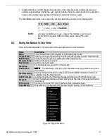
Refer to the following table for the description of mouse operations in Live View mode: 

Name 

Description 

Menu 

Enter the main menu of the system by right clicking the mouse 

Single Screen 

Switch to the single full screen by choosing channel number from the drop-down list 

Multi-Screen 

Adjust the screen layout by selecting from the drop-down list. 

Previous Screen 

Switch to the previous screen 

Next Screen 

Switch to the next screen 

Start/Stop 
Auto-Switch 

Enable/disable the auto-switch of the screens 

NOTE:

NOTE:

NOTE:

NOTE:


The 

dwell time

 of the live view configuration must be set before using Start 

Auto-Switch


Start Recording 

Start recording all channels; Continuous Record and Motion Detection Record are 

selectable from the drop-down list 

Add IP Camera 

A shortcut to enter the IP camera management interface.(For HDVR series only) 

Playback 

Enter the playback interface and start playing back the video of the selected channel 

immediately. 

PTZ Control 

Shortcut to enter the PTZ control interface of the selected camera 

Output Mode 

Output Mode is configurable with Standard, Bright, Gentle, and Vivid options 


Figure 42, Right-Click Menu


Содержание DS-90 HUHI-F8/N Series

Страница 1: ...DS 90xxHUHI F8 N Digital Video Recorder User Manual 041717NA ...

Страница 2: ...LL PROVIDE TIMELY TECHNICAL SUPPORTS IF REQUIRED SURVEILLANCE LAWS VARY BY JURISDICTION PLEASE CHECK ALL RELEVANT LAWS IN YOUR JURISDICTION BEFORE USING THIS PRODUCT IN ORDER TO ENSURE THAT YOUR USE CONFORMS THE APPLICABLE LAW HIKVISION SHALL NOT BE LIABLE IN THE EVENT THAT THIS PRODUCT IS USED WITH ILLEGITIMATE PURPOSES IN THE EVENT OF ANY CONFLICTS BETWEEN THIS MANUAL AND THE APPLICABLE LAW THE ...

Страница 3: ...iled information Do not connect several devices to one power adapter as adapter overload may cause over heating or a fire hazard Please make sure that the plug is firmly connected to the power socket If smoke odor or noise rise from the device turn off the power at once and unplug the power cable and then please contact the service center Preventive and Cautionary Guidelines Before connecting and ...

Страница 4: ...g the mouse and PTZ tracing by dragging mouse HDD Management Each disk with a maximum of 6 TB storage 8 network disks 8 NAS disks 8 IP SAN disks or n NAS disks m IP SAN disks n m 8 can be connected Remaining recording time of the HDD can be viewed Supports cloud storage S M A R T and bad sector detection HDD sleeping function HDD property redundancy read only read write R W HDD group management HD...

Страница 5: ... quick access to menu Password can be shown in clear text by clicking icon GUID file password key can be exported for easy password reset Network Functions One self adaptive 10M 100M 1000M network interface 16 channel or 1 self adaptive 10M 100Mbps network interface 4 8 channel IPv6 is supported TCP IP protocol PPPoE DHCP DNS NTP SADP SMTP NFS iSCSI UPnP and HTTPS are supported Supports access by ...

Страница 6: ...VR 14 5 1 4 Rebooting the DVR 15 5 2 Activating the Device 15 6 Using the Unlock Pattern for Login 18 6 1 Configuring the Unlock Pattern 18 6 2 Logging in via Unlock Pattern 19 7 Login and Logout 20 7 1 User Login 20 7 2 User Logout 23 8 Adding Cameras 23 8 1 Analog Cameras 23 8 1 1 Adding Analog Cameras 23 8 1 2 Disabling Analog Cameras To Increase Number of IP Cameras 23 8 2 IP Cameras 24 8 2 1 ...

Страница 7: ...ncoding Parameters 52 11 1 1 Before Starting 52 11 2 Configuring Recording and Capture Schedule 57 11 2 1 Set the Record Schedule 57 11 2 2 Draw the Schedule 59 11 3 Configuring Motion Detection Recording and Capture 60 11 4 Configuring Alarm Triggered Recording 61 11 5 Configuring Event Recording 63 11 6 Configuring Manual Recording and Continous Capture 64 11 7 Configuring Holiday Recording 64 1...

Страница 8: ...16 Network Settings 96 16 1 Configuring General Settings 96 16 2 Configuring Advanced Settings 97 16 2 1 Configuring PPPoE Settings 97 16 2 2 Register a HIK Connect P2P Cloud Service Account 98 16 2 3 Enable Hik Connect P2P on the NVR 99 16 2 4 Add the NVR to the Hik Connect Service 99 16 2 5 Accessing the NVR 100 16 2 6 Configuring NTP Server 100 16 2 7 Configuring NAT 101 16 2 8 Configuring More...

Страница 9: ...onfiguring POS Settings 132 19 2 Configuring Overlay Channel 137 19 3 Configuring POS Alarm 137 20 Camera Settings 140 20 1 Configuring OSD Settings 140 20 2 Configuring Privacy Mask 141 20 3 Configuring Video Parameters 142 20 3 1 Configuring Image Settings 142 20 3 2 Configuring Camera Parameters Settings 144 21 DVR Management and Maintenance 145 21 1 Viewing System Information 145 21 2 Searchin...

Страница 10: ...anel Lock Locks access to hard drives 4 DVD Bay For DVD drive 5 Number Buttons To enter numbers 6 USB Ports Connects USB mouse or USB flash memory devices 7 Function Buttons Use to access device functions 8 Direction Buttons Move up down left right 9 Enter Confirms menu selection Ticks checkbox fields In Playback mode plays or pauses video In Single Play mode advances video a single frame 10 Scrol...

Страница 11: ...tch for turning device on off 12 Power Input 100 to 240 VAC power 13 Video In BNC connectors for video input 14 USB Interface Connect to USB mouse or USB flash memory devices 15 Video Out BNC connector for video output 16 HDMI1 HDMI video output connector 17 VGA DB 15 connector for VGA output to display local video output and menu 18 LAN1 Connector for LAN Local Area Network 19 Alarm In Connectors...

Страница 12: ...UM DS 90xxHUHI F8 N User Manual 041717NA 11 1 3 Menu Tree ...

Страница 13: ... files In Live View mode buttons cycle through channels In PTZ control mode controls movement of the PTZ camera ENTER Button Confirms selection in any of the menu modes Can also be used to tick checkbox fields In Playback mode plays or pauses the video In single frame Playback mode advance video a single frame 5 PTZ Button In Auto switch mode stops starts auto switch 6 DEV Enables Disables Remote ...

Страница 14: ...ar 3 button Left Right Scroll wheel USB mouse wired or wireless can also be used with this DVR 3 1 Attach Mouse 1 Plug USB mouse into one of the USB interfaces on the front panel of the DVR 2 The mouse should automatically be detected If the mouse is not detected the two devices may not be compatible Refer to the recommended device list from your provider 3 2 Mouse Operation Name Action Descriptio...

Страница 15: ...efore Starting Check that the voltage of the external power supply is the same with the DVR s requirement and the ground connection is working properly 5 1 2 Starting the DVR 1 Check that the power supply is plugged into an electrical outlet It is HIGHLY recommended that an Uninterruptible Power Supply UPS be used in conjunction with the device 2 Turn on the power switch on the rear panel 16 chann...

Страница 16: ...hutdown menu you can also reboot the DVR 1 Enter the Shutdown menu by clicking Menu Shutdown 2 Click the Logout button to log out or the Reboot button to reboot the DVR 5 2 Activating the Device For first time access you must activate the device by creating an admin password You can also activate the device via a Web browser the SADP program or client software 1 Input the same password in the Crea...

Страница 17: ...Click OK to save the password and activate the device NOTE Clear text password is supported Click the icon and you will see clear text of the password Click the icon again and the the password again becomes hidden If you update an old version to the new version the following dialog box will pop up once the device starts up Click YES and follow the prompts to set a strong password Figure 8 Password...

Страница 18: ...Home PO3243 5 Double click on the new folder to switch to that location for saving 6 Click the Export button to export the GUID file to the USB flash disk The system will show the saved GUID file NOTE The first nine digits after GUID_ is the serial number of the unit from which the GUID was exported Digits after the serial number are the date of export If multiple GUIDs exist for the same unit alw...

Страница 19: ...following interface to configure the device unlock pattern Figure 11 Set Unlock Pattern 1 Use the mouse to draw a pattern among the nine dots on the screen Release the mouse when the pattern is done Figure 12 Draw the Pattern NOTE Connect at least four dots to draw the pattern Each dot can be connected once only 2 Draw the same pattern again to confirm it When the two patterns match the pattern is...

Страница 20: ...ent you must set the pattern again Figure 14 Reset the Pattern 6 2 Logging in via Unlock Pattern NOTE Only the admin user has permission to unlock the device Configure the pattern before unlocking 1 Right click the mouse on the screen and select the menu to enter the interface Figure 15 Draw the Unlock Pattern ...

Страница 21: ...rent from the pattern you have configured try again If you have drawn the wrong pattern seven times the account will be locked for one minute Figure 16 Normal Login Dialog Box 7 Login and Logout 7 1 User Login You must log in to the device before operating the menu and other functions 1 Select the User Name in the drop down list Figure 17 Login Interface 2 Input the Password 3 Click OK to log in N...

Страница 22: ... entered the wrong password five times the account will be locked for 60 seconds Figure 18 User Account Protection for the Admin Figure 19 User Account Protection for the Operator 4 Optional If you forget the password click Forget Password to pop up the Import GUID interface Figure 20 Import GUID File 5 Select the GUID file from the USB flash disk and click Import to display Reset Password interfa...

Страница 23: ...k the OK button and the Attention box pops up to remind you to duplicate the password of the device to IP cameras that are connected with default protocol Click Yes to duplicate the password or No to cancel it Figure 23 Duplicate the Password NOTE If you want to retrieve the password when you forget it you must export the GUID file first Once the password has been reset the GUID file becomes ineff...

Страница 24: ...eras 8 1 1 Adding Analog Cameras Analog cameras are enabled by default no further action is required 8 1 2 Disabling Analog Cameras To Increase Number of IP Cameras NOTE Disabling an analog camera allows substitution of a network IP camera in its place up to 10 IP cameras maximum for DS 7308HUHI F4 N and up to 18 IP cameras maximum for DS 7316HUHI F4 N 1 Go to MENU CAMERAS ANALOG TAB 2 Analog Came...

Страница 25: ...ellow are cameras that have been detected on the network but not added to view on the DVR Cameras listed in white are cameras that have been added to view on the DVR NOTE If the camera you want to add does not appear on the list make sure it is on the same network as the DVR If it is onthe same network you can add the camera manually by pressing the CUSTOM ADDING button to display the Add IP Camer...

Страница 26: ...ra s password against its own password If the IP Camera s and DVR s Passwords Match Camera name will turn white and the camera will be added to the DVR If the IP Camera s and DVR s Passwords Do Not Match The cameras will be added with incorrect passwords and will be locked If the password of the camera does not match the password of the NVR see Custom Adding IP Camera section below NOTE If the cam...

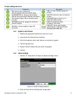
Страница 27: ...ADDING button to add the cameramanually 2 In the Add IP Camera Custom window enter the following information IP Camera Address Protocol Management Port User Name Admin Password 3 Press Add button Figure 27 Add IP Camera Custom Window 8 2 3 Modify IP Camera Settings 1 Go to MENU CAMERAS IP CAMERA 2 Click the following icons to managecameras NOTE To change camera name go to OSD ...

Страница 28: ...er information into the following fields asappropriate Icon Explanation Icon Explanation EDIT Pen Press to edit basic IP camera parameters must be in LAN2 range ADD Press to add the detected IP camera DISCONNECTED Camera is disconnected click the icon to get camera s exception information DELETE Trash Can Press to delete the camera PLAY Right Triangle Play connected camera s live video ADVANCED Ge...

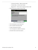
Страница 29: ...camera management port default 8000 3 Click the Password tab to display the Passwordwindow Figure 29 Advanced Settings Password 4 Enter current password in Current Password field 5 Enter new password in New Password field 6 Re type new password in Confirm field 7 Click on the Apply button to validate the new password 8 Click the OK button to accept the new password ...

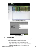
Страница 30: ... activated before first use To activate a camera before adding it to the DVR 1 View the status of the camera in the Camera List Security column Active Camera has been activated no further activation necessary Inactive Camera is inactive it must be activated before adding it to the DVR Strong Medium Weak Risky Displays the camera s password strength ...

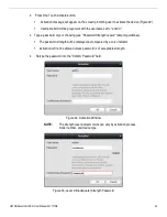
Страница 31: ...ssword of your choosing see Password Strength Levels table for guidelines The password strength will be displayed accompanied by a color indicator Activation will not be allowed unless password is of acceptable strength 4 Retype the password into the Confirm Password field Figure 32 Activation Window NOTE The strength level indicator colors can vary by activation process model number and device ty...

Страница 32: ...UM DS 90xxHUHI F8 N User Manual 041717NA 31 Figure 34 Invalid Password Message Figure 35 Level 1 Password Strength Figure 36 Level 2 Password Strength ...

Страница 33: ...al 041717NA 32 Figure 37 Level 3 and Level 4 Password Strength 5 After an acceptable password has been created a confirmation message will appear Figure 38 6 Press the OK button to proceed Figure 38 Activation Confirmation Message ...

Страница 34: ... a Level 2password Password contains two types of characters The combination is neither number lowercase letter nor number uppercase letter and the password length is at least eight characters This type of password will be accepted Level 3 Strong DVRs will accept a Level 3password Password contains more than three types of characters and the password length is at least eight characters This type o...

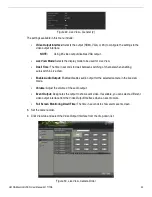
Страница 35: ...U SYSTEM CONFIGURATION LIVE VIEW GENERAL 2 Set the following values as desired Video Output Interface Use pull down menu to select the monitor to use for Live View Live View Mode Use pull down menu to select the monitor view layout Dwell Time Use pull down menu to select the seconds to wait between Live View screens Enable Audio Output Check to enable audio if the camera is so equipped Volume Clic...

Страница 36: ...k a camera on the camera list on the left of the screen to assign the camera to the highlighted screen position 6 Repeat for all screen positions 7 Press the Apply button 9 1 3 Channel Zero Encoding Channel Zero Encoding combines all video streams into one lower resolution lower bandwidth channel Do the following to enable Channel Zero Encoding 1 Go to MENU SYSTEM CONFIGURATION LIVE VIEW CHANNEL Z...

Страница 37: ...cord Event Exception motion detection sensor alarm or exception information 9 2 Operations in Live View Mode In Live View mode there are many functions provided The functions are listed below Single Screen show only one screen on the monitor Multi screen show multiple screens on the monitor simultaneously Start Auto Switch the screen is auto switched to the next one You must set the dwell time for...

Страница 38: ...ght clicking the mouse Single Screen Switch to the single full screen by choosing channel number from the drop down list Multi Screen Adjust the screen layout by selecting from the drop down list Previous Screen Switch to the previous screen Next Screen Switch to the next screen Start Stop Auto Switch Enable disable the auto switch of the screens NOTE NOTE NOTE NOTE The dwell time of the live view...

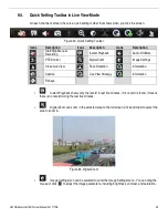
Страница 39: ...m Image Settings Close Live View Face Detection Information Capture Live View Strategy Information Fisheye Instant Playback shows only the record in last five minutes If no record is found it means there is no record during the last five minutes Digital Zoom can zoom in the selected area to the full screen Click and draw to select the area to zoom in Figure 44 Digital Zoom Image Settings icon can ...

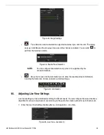
Страница 40: ... when it is supportsed by the connected camera Move the mouse onto the Information icon to show the real time stream information including the frame rate bit rate resolution and stream type Figure 47 Information 9 5 Adjusting Live View Settings Live View settings can be customized according to different needs You can configure the output interface dwell time for screen to be shown mute or turning ...

Страница 41: ...n switching of channels when enabling auto switch in Live View Enable Audio Output Enables disables audio output for the selected camera in the live view mode Volume Adjust the volume of the audio output Event Output Designates the output to show event video If available you can select a different video output interface from the Video Output Interface when an event occurs Full Screen Monitoring Dw...

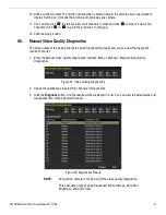
Страница 42: ...quality of the analog channels can be diagnosed manually and you can view the diagnostic results from a list 1 Enter the Manual Video Quality Diagnostics interface Menu Manual Manual Video Quality Diagnostics Figure 51 Video Quality Diagnostics 2 Check the checkboxes to select the channels for diagnostics 3 Click the Diagnose button and the results will be displayed in a list You can view the vide...

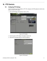
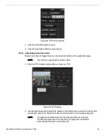
Страница 43: ...arameters for PTZ The configuring of the PTZ parameters should be done before you control the PTZ camera 1 Enter the PTZ Settings interface Menu Camera PTZ Figure 53 PTZ Settings 2 Select the camera for PTZ setting in the Camera drop down list 3 Click the PTZ Parameters button to set the PTZ parameters Figure 54 PTZ General ...

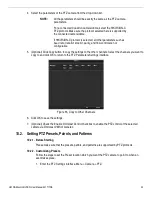
Страница 44: ...Copy button to copy the settings to the other channels Select the channels you want to copy to and click OK to return to the PTZ Parameters Settings interface Figure 55 Copy to Other Channels 6 Click OK to save the settings 7 Optional Check the Enable Omnicast Control checkbox to enable the PTZ control of the selected camera via Omnicast VMS of Genetec 10 2 Setting PTZ Presets Patrols and Patterns...

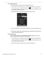
Страница 45: ... clear the location information of the preset or click the Clear All button to clear the location information of all the presets 10 2 3 Calling Presets This feature enables the camera to point to a specified position such as a window when an event takes place 1 Click the PTZ button in the lower right corner of the PTZ setting interface or press the PTZ button on the front panel or click the PTZ Co...

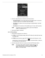
Страница 46: ... connected Coaxitron camera dome Use the directional buttons on the PTZ control panel to operate the menu 10 2 4 Customizing Patrols Patrols can be set to move the PTZ to different key points and have it stay there for a set duration before moving on to the next key point The key points are corresponding to the presets The presets can be set following the steps above in Customizing Presets 1 Enter...

Страница 47: ...he next key point to the patrol or click the OK button to save the key point to the patrol 6 You can delete all the key points by clicking the Clear button for the selected patrol or click the Clear All button to delete all the key pints for all patrols 10 2 5 Calling Patrols Calling a patrol moves the PTZ according the predefined patrol path 1 Click the PTZ button in the lower right corner of the...

Страница 48: ...art button and click corresponding buttons in the control panel to move the PTZ camera Click the Stop button to stop it The PTZ movement is recorded as the pattern 10 2 7 Calling Patterns Follow the procedure to move the PTZ camera according to the predefined patterns 1 Click the PTZ button in the lower right corner of the PTZ Settings interface or press the PTZ button on the front panel or click ...

Страница 49: ... function is supported by certain models 1 Enter the PTZ Settings interface Menu Camera PTZ Figure 63 PTZ Settings 2 Use the directional button to wheel the camera to the location where you want to set the limit and click the Left Limit or Right Limit button to link the location to the corresponding limit NOTE NOTE NOTE NOTE The speed dome starts linear scan from the left limit to the right limit ...

Страница 50: ...button to start the linear scan and click the Linear Scan button again to stop it 4 Click the Restore button to clear the defined left limit and right limit data and the dome needs to reboot to have settings take effect 10 2 10 One Touch Park Certain speed dome models can be configured to start a predefined park action scan preset patrol etc automatically after a period of inactivity park time 1 C...

Страница 51: ...t value is 5s 4 Click the button again to inactivate it 10 2 11 PTZ Control Panel 1 Enter the PTZ control panel in one of two ways OPTION 1 In the PTZ Settings interface click the PTZ button on the lower right corner next to the Back button OPTION 2 In Live View mode press the PTZ Control button on the front panel or on the remote control or choose the PTZ Control icon in the quick setting bar or ...

Страница 52: ...scription Icon Description Direction button and the auto cycle button Zoom Focus Iris Zoom Focus Iris The speed of the PTZ movement Light on off Wiper on off 3D Zoom Image Centralization Menu Switch to the PTZ control interface Switch to the one touch control interface Switch to the general settings interface Exit Minimize windows ...

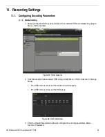
Страница 53: ...l an HDD and initialize it by going to Menu HDD General Figure 67 HDD General 2 Click the Advanced tab and select HDD storage mode Menu HDD Advanced Storage Mode If the HDD mode is Quota set the maximum record capacity If the HDD mode is Group set the HDD group Figure 68 HDD Advanced 3 Enter the Record Parameters interface to configure the encoding parameters Menu Record Parameters ...

Страница 54: ...tion will be adjusted to 3 MP 8 MP if 8 MP IP camera and the frame rate will be adjusted to 12 fps automatically if the resolution and frame rate are not configured manually If the 3 MP camera is connected to a channel that supports up to 1080p signal input it will switch to 1080p signal input When the 3 MP signal is switched to 1080p signal PAL will be switched to 1080p 25 Hz and NTSC will be swi...

Страница 55: ... average bit rate which refers to the average amount of data transferred per unit of time NOTE When the connected IP camera does not support H 265 only H 264 can be selected for the video encoding 14 Check the Enable H 264 or Enable H 265 checkbox to enable this function Enabling it helps to ensure the high video quality with a lower bitrate NOTE If the connected IP camera supports H 265 and H 265...

Страница 56: ...or the files should be determined by the capacity of the HDDs Redundant Record Saves the record in the redundant HDD Record Audio Enable this feature to record the sound and disable it to record the video without sound Video Stream Main stream Sub stream and Dual stream are selectable for recording When you select sub stream you can record for a longer time with the same storage space NOTE The Red...

Страница 57: ...t C Configure the parameters D Click Apply to save the settings E Optional If the parameters can also be used to other cameras click Copy to copy the settings to other channels NOTE When a 3 MP signal input is connected the sub stream frame rate cannot exceed 12 fps 19 Set parameters for capture A Select the Capture tab Figure 73 Capture Settings B Select a camera in the camera drop down list C Co...

Страница 58: ...igure schedule for both recording and capture To schedule automatic capture choose the Capture tab in the Schedule interface 11 2 1 Set the Record Schedule The camera will automatically start stop recording according to the configured schedule 1 Enter the Record Schedule interface Menu Record Capture Schedule Figure 74 Record Schedule 2 Different recording types are marked in different color icons...

Страница 59: ... another schedule leave the All Day checkbox blank and set the Start End time This allows for precise start and end times versus using the drag and drop scheduling Figure 76 Edit Schedule Set Time Period NOTE Up to eight periods can be configured for each day Time periods cannot overlap To enable Event Motion Alarm M A motion or alarm and M A motion and alarm triggered recording configure the moti...

Страница 60: ...ay option is available when you enable holiday schedule in Holiday settings 6 Click OK to save setting and back to upper level menu 11 2 2 Draw the Schedule 1 Click on the color icon to select a record type in the event list on the right side of the interface Figure 78 Draw the Recording Schedule ...

Страница 61: ...the Record Schedule interface to save the settings 11 3 Configuring Motion Detection Recording and Capture Set the motion detection parameters In Live View mode once a motion detection event takes place the DVR will analyze it and perform actions to handle it Enabling motion detection can trigger certain channels to start recording or trigger full screen monitoring audio warning notify the surveil...

Страница 62: ... 81 Motion Detection Mask D Click Set to display the Motion Detection sub menu Figure 82 Motion Detection Settings E Select the channels which you want the motion detection event to trigger recording F Click Apply to save the settings G Click OK to back to the upper level menu H Exit the Motion Detection menu 3 Configure the Schedule choosing Motion as the record type 11 4 Configuring Alarm Trigge...

Страница 63: ...rm Input 3 Select Alarm Input number and configure alarm parameters 4 Choose N O normally open or N C normally closed for alarm type 5 Check the Setting checkbox 6 Click the Set button Figure 85 Alarm Handling 7 Choose the alarm triggered recording channel 8 Check the checkbox to select channel 9 Click Apply to save settings ...

Страница 64: ...e 11 5 Configuring Event Recording Event triggered recording can be configured through the menu including 1 ch VCA line crossing detection and intrusion detection Channels with audio supports audio exception detection 1 Enter the VCA settings interface and select a camera for the VCA settings Menu Camera VCA Figure 87 VCA Settings 2 Configure the detection rules for VCA events 3 Click the icon to ...

Страница 65: ...ecording is prior to scheduled recording 1 Enter the Manual Record interface Menu Manual Figure 89 Manual Record 2 Enable manual record 3 Click the status icon before camera number to change it to or click the status icon of Analog to enable manual record of all channels 4 To disable manual record click the status icon to change it to or click the Analog status icon to disable manual record of all...

Страница 66: ...lect Mode from the drop down list NOTE There are three holiday schedule date formats By Month By Week and By Date are selectable 7 Set the start and end date 8 Click Apply to save settings 9 Click OK to exit the Edit interface 10 Configure the record schedule Refer to Configuring Recording Schedule You may choose Holiday in the Schedule drop down list or you can draw the schedule on the Holiday ti...

Страница 67: ...8 Configuring HDD Group You can group the HDDs and save the record files in a certain HDD group 1 Enter HDD setting interface Menu HDD Advanced 2 Select Storage Mode tab 3 Check whether the storage mode of the HDD is Group If not set it to Group 4 Select General in the left bar 5 Click to enter editing interface 6 Configure HDD group A Choose a group number for the HDD group B Click Apply to save ...

Страница 68: ...igure the recording settings 11 9 Files Protection You can lock the recorded files or set the HDD property to Read only to protect the record files from being overwritten 11 9 1 Protect File by Locking the Record Files 1 Enter the Export Settings interface Menu Export Figure 94 Export 2 Select the channels you want to investigate by checking the checkboxes 3 Configure the record mode record type f...

Страница 69: ...ding is not completed cannot be locked 6 Click to change it to to unlock the file and the file is not protected 11 9 2 Protect File by Setting HDD Property to Read Only 1 Enter the HDD setting interface Menu HDD 2 Set the HDD storage mode to Group Figure 96 HDD General 3 Click to edit the HDD you want to protect Figure 97 HDD General Editing 4 Set the HDD to Read only 5 Click OK to save settings a...

Страница 70: ...Enabling for All Cameras 1 Enter the Record menu Menu Record 2 Click Advanced to enter the Advanced Settings interface Figure 98 Record Information 3 Click Enable to enable H 264 for all cameras and the following attention box pops up Figure 99 Attention Box 4 Click Yes to enable the function and reboot the device to have new settings taken effect NOTE If H 264 is already enabled for all analog ca...

Страница 71: ...og cameras when you click the Disable button the following attention box pops up to remind you that H 264 is already disabled Figure 103 Attention Box 13 Playback 13 1 Playing Back Record Files 13 1 1 Instant Playback by Channel Play back the recorded video files of a specific channel in the live view mode Channel switch is supported 1 Choose a channel in live view mode and click the button in the...

Страница 72: ...nder Live View 13 1 2 Play Back by Time Play back video files recorded in specified time duration Multi channel simultaneous playback and channel switch are supportsed 1 Enter Playback interface Menu Playback 2 Check the checkbox of channel s in the channel list then double click to select a date on the calendar ...

Страница 73: ... 2 Playback Interface You can select the main stream or sub stream from the drop down list for playback You can also use the toolbar in the bottom part of Playback interface to control playing progress as shown in the following figure Figure 107 Playback Interface 1 Select the channel s if you want to switch playback to another channel or execute simultaneous playback of multiple channels Figure 1...

Страница 74: ...vent recording motion alarm motion alarm motion alarm VCA Playback progress bar use the mouse to click any point of the progress bar to locate special frames 13 3 Playing Back by Event Search Play back record files on one or several channels searched out by restricting event type motion detection alarm input or VCA Channel switch is supported 1 Enter the Playback interface Menu Playback 2 Click an...

Страница 75: ... one channel for playback or select multiple channels for synchronous playback The maximum number of channels for synchronous playback varies by model Figure 110 Select Channels for Synchronous Playback 6 On the Event Playback interface you can select the main stream or sub stream from the drop down list for playback 7 The toolbar in the bottom part of Playback interface can be used to control pla...

Страница 76: ...0 05 8 Click the or button to select the previous or next event 13 4 Playing Back by Tag Video tags allow you to record related information such as people and locations at a certain time point during playback You can also use video tag s to search for record files and position time points 13 4 1 Before Playing Back by Tag 1 Enter the Playback interface Menu Playback 2 Search and play back the reco...

Страница 77: ...erface 7 Choose channels edit start time and end time and then click Search to enter Search Result interface NOTE Enter keyword in the textbox to search the tag on your command Figure 115 Video Search by Tag 8 Click button to play back the file 9 Click the Back button to return to the search interface NOTE Pre play and post play can be configured Click or button to select the previous or next tag ...

Страница 78: ...u Maintenance Log Information Figure 116 System Log Search Interface 2 Click Log Search tab to enter System Log Search interface 3 Set search time and type and click Search button Figure 117 Result of System Log Search 4 Choose a log with record file and click button to enter Playback interface NOTE If there is no record file at the timepoint of the log a No result found message will pop up ...

Страница 79: ... down list in the upper left corner of the page to enter the Sub periods Playback interface 3 Select a date and start playing the video file 4 Select the Split Screen Number from the drop down list Up to 16 screens are configurable Figure 119 Interface of Sub periods Playback NOTE According to the defined number of split screens the video files on the selected date can be divided into average segm...

Страница 80: ...ure 120 Interface of External File Playback 13 8 Auxiliary Playback Functions 13 8 1 Playing Back Frame by Frame Play video files frame by frame to check video image details when abnormal events happen 1 Go to Playback interface and click button until the speed changes to Single frame 2 One click on the playback screen represents playback or adverse playback of one frame You can use button in tool...

Страница 81: ... Channels You can play back record files of multi channel reversely Up to 16 channels of simultaneous reverse playback is supported 1 Enter the Playback interface Menu Playback 2 Check more than one checkboxes to select multiple channels and click to select a date on the calendar Figure 122 4 ch Synchronous Playback Interface 3 Click to play back the record files reversely ...

Страница 82: ... HDD 14 2 1 Back Up Using USB Flash Drives and USB HDDs 1 Enter Export interface Menu Export Normal Picture 2 Select the cameras to search 3 Select Main Sub Stream and Recording Mode Figure 123 Normal Video Search for Backup 4 The matched video files are displayed in Chart or List display mode 5 Click to play the record file if you want to check it 6 Check the checkbox before the video files you w...

Страница 83: ...o files for backup and enter the Export interface Figure 125 Export by Normal Video Search Using USB Flash Drive 8 Select the backup device from the drop down list you can also select the file format to filter the files existing in the backup device 9 Select the saving type 10 Click the Export button on the Export interface to start the backup process On the pop up message box select to export the...

Страница 84: ...es USB flash drives USB HDDs USB writer SATA writer or eSATA HDD Quick Backup and Normal Backup are supported 1 Enter Export interface Menu Export Event 2 Select the cameras to search 3 Select the event type to alarm input motion or VCA Figure 128 Event Search for Backup 4 Set search condition and click Search button to enter the search result interface The matched video files are displayed in Cha...

Страница 85: ...ayback using USB devices USB flash drives USB HDDs USB writer or SATA writer 1 Enter Playback interface 2 During playback use the or buttons in the playback toolbar to start or stop clipping record file s 3 Click to enter the file management interface Figure 130 Video Clips Export Interface 4 Export the video clips in playback 14 5 Managing Backup Devices Manage USB flash drives USB HDDs and eSATA...

Страница 86: ...to delete it 4 Click Erase button if you want to erase the files from a re writable CD DVD 5 Click Format button to format the backup device NOTE If the inserted storage device is not recognized click the Refresh button reconnect the device or check for compatibility from vendor 15 Alarm Settings 15 1 Setting Motion Detection 1 Enter the Camera Management Motion Detection interface Menu Camera Mot...

Страница 87: ...133 Set Detection Area and Sensitivity 8 Click Trigger Channel tab and select one or more channels that will start to record or become full screen monitoring when a motion alarm is triggered Figure 134 Set Trigger Camera of Motion Detection 9 Select Arming Schedule tab to set the channel s arming schedule 10 Choose one day of a week and up to eight time periods can be set within each day Or click ...

Страница 88: ...nnel repeat the above steps or just copy above settings to it NOTE You are not allowed to copy the Trigger Channel action 15 2 Setting Sensor Alarms Set up handling method of an external sensor alarm 1 Enter Alarm Settings of System Configuration and select an alarm input Menu Record Configuration Trigger 2 Select Alarm Input tab to enter Alarm Input Settings interface Figure 136 Alarm Status Inte...

Страница 89: ...rming Schedule of Alarm Input 8 Select Linkage Action tab to set up alarm response actions of the alarm input 9 Repeat the above steps to set up arming schedule of other days of a week You can also use Copy button to copy an arming schedule to other days 10 If necessary select PTZ Linking tab and set PTZ linkage of the alarm input 11 Set PTZ linking parameters and click the OK button to complete t...

Страница 90: ... another alarm input repeat the above steps or just copy above settings to it Figure 139 Copy Settings of Alarm Input 15 3 Detecting Video Loss Detect video loss of a channel and take alarm response action s 1 Enter Camera Management Video Loss interface Menu Camera Video Loss 2 Select a channel you want to detect ...

Страница 91: ...ds can be set within each day Or you can click the Copy button to copy the time period settings to other day s NOTE Time periods must not repeat or overlap Figure 141 Set Arming Schedule of Video Loss 9 Repeat the above steps to set arming schedule of other days of a week You can also use Copy button to copy an arming schedule to other days 10 Select Linkage Action tab to set up alarm response act...

Страница 92: ... the Enable Video Tampering Detection checkbox 4 Drag the sensitivity bar to choose sensitivity level 5 Click Set button to set video tampering handling method Set channel arming schedule and alarm response actions 6 Click Arming Schedule tab to set the response action arming schedule 7 Choose one day of a week and up to eight time periods can be set within each day NOTE Time periods must not repe...

Страница 93: ...y Diagnostics 2 Select a channel you want to detect video tampering Figure 144 Video Quality Diagnostics Interface 3 Check the Enable Video Quality Diagnostics checkbox NOTE To enable video quality diagnostics the function must be supported by the selected camera 4 Enable and set the diagnostic type threshold blurred Image abnormal brightness and color cast 5 Check the corresponding checkbox of th...

Страница 94: ...vate settings 13 Optional copy the same settings to other cameras by clicking the Copy button 15 6 Handling Exceptions Exception settings refer to the handling method of various exceptions HDD Full The HDD is full HDD Error Writing HDD error unformatted HDD etc Network Disconnected Disconnected network cable IP Conflicted Duplicated IP address Illegal Login Incorrect user ID or password Input Reco...

Страница 95: ...ckbox to display the Event Exception icon when an exceptional event occurs Click the Set Button to display the detailed event hint Figure 147 Event Hint Settings NOTE Click the icon in the Live View interface to view detailed information of the exceptional event Click the Set button to display the detailed event hint ...

Страница 96: ... an interval of 10 seconds default dwell time A different dwell time can be set by going to Menu Configuration Live View Auto Switch Auto switch will terminate once the alarm stops and will return to the Live View interface Audible Warning Triggers an audible beep when an alarm is detected Notify Surveillance Center Sends an exception or alarm signal to remote alarm host when an event occurs The a...

Страница 97: ... Time periods must not repeat or overlap Figure 150 Set Arming Schedule of Alarm Output 5 Repeat the above steps to set arming schedule for other days of a week You can also click the Copy button to copy an arming schedule to other days 6 Click the OK button to complete the alarm output arming schedule setting 7 Click the Apply button to save the settings 16 Network Settings 16 1 Configuring Gener...

Страница 98: ...P address and other network settings automatically from that server If DHCP is enabled check Enable DNS DHCP checkbox or uncheck it and edit the Preferred DNS Server and Alternate DNS Server 4 After having configured the general settings click the Apply button to save the settings 16 2 Configuring Advanced Settings 16 2 1 Configuring PPPoE Settings The DVR allows access by Point to Point Protocol ...

Страница 99: ...n Account 2 Check the Read and Agree checkbox 3 Register the Account Using Mobile Phone Number 1 Click Register by Mobile Phone Number 2 Click on your country to display checkmark then click Finish 3 Enter your mobile phone number then press Get Verification Code button 4 Check your phone for the verification code that was texted and enter it into the Input the received verification code field the...

Страница 100: ...ile app you must add the NVR 1 Login to Hik Connect mobile app with your user name e mail or mobile number and password 2 On the Home screen click the button upper right corner 3 Enter the device s information If you have device s QR Code Use QR Code Scanner to scan QR Code If you do not have device s QR Code Enter device information manually 1 Click the Edit pencil icon on top right 2 Enter devic...

Страница 101: ...TE For more help see the help file on the Hik Connect website at www hik connect com 16 2 6 Configuring NTP Server A Network Time Protocol NTP Server can be configured on your DVR to ensure accuracy of the system date time 1 Enter the Network Settings interface Menu Configuration Network 2 Select the NTP tab to enter the NTP Settings interface Figure 154 NTP Settings Interface 3 Check the Enable N...

Страница 102: ...s etc Use the UPnP function to quickly connect the device to the WAN via a router without port mapping NOTE To enable the UPnP function of the device you must enable the UPnP function of the router to which your device is connected When the network working mode of the device is set as multi address the Default Route of the device should be in the same network segment as that of the LAN IP address ...

Страница 103: ... the port No for port mapping in the router The RTSP port No value should be 554 or between 1024 and 65535 while the value of the other ports should be between 1 and 65535 and the values must be different from each other If multiple devices are configured for the UPnP settings under the same router the value of the port No for each device should be unique Figure 156 External Port Settings Dialog B...

Страница 104: ...figured to realize live view for more than the maximum number of cameras through network A multicast address spans the Class D IP range of 224 0 0 0 to 239 255 255 255 It is recommended to use the IP address ranging from 239 252 0 0 to 239 255 255 255 When adding a device to the CMS Client Management System software the multicast address must be the same as the device s multicast IP RTSP Port The ...

Страница 105: ...th which protects against man in the middle attacks Perform the following steps to set the https port number Example If you set the port number to 443 and the IP address is 192 0 0 64 you may access the device by inputting https 192 0 0 64 443 via the Web browser NOTE The HTTPS port can be configured only through the Web browser 1 Open Web browser input the IP address of device and the Web server ...

Страница 106: ...ion 6 Click the Save button to save the settings 16 2 10 Configuring E Mail The system can be configured to send an e mail notification to all designated users if an event is detected e g an alarm or motion event is detected etc Before configuring the e mail settings the DVR must be connected to a local area network LAN that maintains an SMTP mail server The network must also be connected to eithe...

Страница 107: ...P address or host name e g smtp 263xmail com SMTP Port The SMTP port The default TCP IP port used for SMTP is 25 Enable SSL optional Click the checkbox to enable SSL if required by the SMTP server Sender The name of sender Sender s Address The e mail address of sender Select Receivers Select the receiver Up to three receivers can be configured Receiver The name of the e mail receiver Receiver s Ad...

Страница 108: ...k Traffic You can check the network traffic to obtain real time information of DVR such as linking status MTU sending receiving rate etc 1 Enter the Network Traffic interface Menu Maintenance Net Detect Figure 164 Network Traffic Interface 2 You can view the sending rate and receiving rate information on the interface The traffic data is refreshed every second 16 3 Configuring Network Detection Yo...

Страница 109: ...red network data packet can be exported to a USB flash disk SATA and other local backup devices 1 Enter the Network Traffic interface Menu Maintenance Net Detect 2 Click the Network Detection tab to enter the Network Detection interface 3 Select the backup device from the Device Name drop down list NOTE Click the Refresh button if the connected local backup device cannot be displayed If it fails t...

Страница 110: ...the network parameters in this interface 1 Enter the Network Traffic interface Menu Maintenance Net Detect 2 Click the Network Detection tab to enter the Network Detection interface 3 Click Status on the right bottom of the interface Figure 168 Checking Network Status 4 If the network is normal the following message box pops out Figure 169 Network Status Checking Result 5 If the message box pops o...

Страница 111: ...n the real time information of the device 1 Enter the Network Statistics interface Menu Maintenance Net Detect 2 Click the Network Stat tab to enter the Network Statistics interface Figure 171 Network Stat Interface 3 View the Remote Live View bandwidth Remote Playback bandwidth and Net Total Idle bandwidth 4 Click Refresh button to get the latest bandwidth statistics ...

Страница 112: ... initialized 1 Enter the HDD Information interface Menu HDD General Figure 172 HDD Information Interface 2 View HDD s Total Capacity Free Space and Remaining Recording Time this uses the average bit rate for the channel allowing smart encoding to increase accuracy 3 Select the HDD to be initialized 4 Click the Init button Figure 173 Confirm Initialization 5 Select the OK button to start initializa...

Страница 113: ...he device and extend its life 7 Click Menu HDD Advanced Figure 176 Enable HDD Sleeping 8 Check default the Enable HDD Sleeping checkbox and the HDDs which are free from working for awhile will be set to sleep 9 Uncheck the Enable HDD Sleeping checkbox and the HDDs will be set to work all the time 17 2 Managing Network HDD You can add an allocated NAS or IP SAN disk to the DVR and use it as a netwo...
Страница 114: ...DD IP address in the text field 2 Click Search to search the available NAS disks 3 Select a NAS disk from the list or manually enter the directory in the NetHDD Directory text field 4 Click OK to add the configured NAS disk NOTE Up to eight NAS disks can be added Figure 179 Add NAS Disk Adding an IP SAN Disk 1 Enter the NetHDD IP address in the text field 2 Click the Search button to find the avai...

Страница 115: ...isk return to the HDD Information menu The added NetHDD will be displayed in the list NOTE If the added NetHDD is uninitialized select it and click the Init button for initialization Figure 181 Initialize Added NetHDD 17 3 Managing HDD Groups 17 3 1 Setting HDD Groups Multiple HDDs can be managed in groups Record video from specified channels to a particular HDD group through HDD settings 1 Enter ...

Страница 116: ...ntion box will pop up Figure 183 Attention for Reboot 4 Click the Yes button to reboot the device and activate the changes 5 After reboot of device enter the HDD Information interface Menu HDD General 6 Select HDD from the list and click the icon to enter the Local HDD Settings interface Figure 184 Local HDD Settings Interface ...

Страница 117: ...itten when the HDD becomes full in overwrite recording mode When the HDD property is set to redundancy the video can be recorded both onto the redundant HDD and the R W HDD simultaneously to ensure high security and reliability of video data 1 Enter the HDD Information interface Menu HDD General 2 Select an HDD from the list and click the icon to enter the Local HDD Settings interface Figure 186 S...

Страница 118: ...Settings Interface 5 Select a camera for which you want to configure quota 6 Enter the storage capacity in the Max Record Capacity GB text field 7 To copy the quota settings of the current camera to other cameras if desired click the Copy button to enter the Copy Camera interface Figure 188 Copy Settings to Other Camera s 8 Select the camera s to be configured with the same quota settings You can ...

Страница 119: ...rive Google Drive or Dropbox Cloud Type from the drop down list Figure 189 Cloud Storage Interface 4 Follow the prompts and use a mobile browser to scan the QR code to log in to the selected cloud to get the authentication code and then copy the authentication code to the Authentication Code text field 5 Click Apply to save the settings and return to the main menu 6 Re enter the cloud storage inte...

Страница 120: ...rage interface and select the camera you have set in the recording schedule interface 10 Select the upload type default is Record in the Upload Type text filed 11 Check the Enable Event Upload checkbox 12 Click Apply to finish the settings Figure 191 Upload to Cloud Storage Interface NOTE Only the sub stream recorded files can be uploaded to the cloud storage ...

Страница 121: ... on the DVR so as to take immediate check and maintenance in case of HDD failure 17 6 1 Checking HDD Status in HDD Information Interface 1 Enter the HDD Information interface Menu HDD General 2 Check the status of each HDD displayed on the list Figure 193 View HDD Status 1 NOTE If the HDD status is Normal or Sleeping it is working normally If the status is Uninitialized or Abnormal initialize the ...

Страница 122: ...e Menu Maintenance HDD Detect 2 Click the S M A R T Settings tab to enter the interface 3 Select the HDD to view its S M A R T information list NOTE To use the HDD even when S M A R T checking has failed check the Continue checkbox Figure 195 S M A R T Settings Interface 17 8 Detecting Bad Sectors You can detect bad HDD sectors 1 Enter the HDD Detect interface Menu HDD HDD Detect 2 Click the Bad S...

Страница 123: ...DD click the Error Info button to view the information 17 9 Configuring HDD Error Alarms You can configure the HDD Uninitialized or Abnormal error alarms 1 Enter the Exception interface Menu Configuration Exceptions 2 Select the HDD Error Exception Type from the drop down list 3 Check the checkbox s to select the HDD error linkage action s Audible Warning Notify Surveillance Center Send E mail and...

Страница 124: ...F8 N User Manual 041717NA 123 Figure 197 Configure HDD Error Alarm 4 When Trigger Alarm Output is selected also select the alarm output to be triggered from the list below 5 Click the Apply button to save the settings ...

Страница 125: ...OTE DS 73xxHUHI F4 N Series DVRs support RAID 0 RAID 1 RAID 5 RAID 6 and RAID 10 array types 18 1 1 Before You Start Install the HDD s properly and it is recommended to use the same enterprise level HDDs including model and capacity for array creation and configuration so as to maintain reliable and stable running of the disks 18 1 2 Introduction The NVR can store the data such as record picture l...

Страница 126: ...terface 2 Check the checkbox of Enable RAID 3 Click the Apply button to save the settings 18 1 4 One Touch Configuration Through one touch configuration you can quickly create the disk array By default the array type to be created is RAID 5 NOTE Before You Start The RAID function should be enabled refer to Section 18 1 3 As the default array type is RAID 5 please install at least three HDDs in you...

Страница 127: ...5 When the array configuration is done click the OK button in the pop up message box to finish 6 You can click Array tab to view the information of the successfully created array NOTE By default one touch configuration creates an array and a virtual disk Figure 202 Array Settings Interface 7 A created array displays as an HDD in the HDD information interface Figure 203 HDD Information Interface 18...

Страница 128: ...nfigure array NOTES If you choose RAID 0 at least two HDDs must be installed If you choose RAID 1 two HDDs need to be configured for RAID 1 If you choose RAID 5 at least three HDDs must be installed If you choose RAID 6 at least four HDDs must be installed If you choose RAID 10 the number of HDDs installed should be even in the range of 4 to 16 4 Click OK button to create array NOTE If the number ...

Страница 129: ... and reliability If there is no disk loss in the array the working status will be Functional if the number of lost disks has exceeded the limit the working status will change to Offline in other conditions the working status is Degraded When the virtual disk is in Degraded status you can restore it to Functional by array rebuilding 18 2 1 Before You Start Make sure the hot spare disk is configured...

Страница 130: ...nterface NOTE If there is no hot spare disk after rebuilding it is recommended to install a HDD into the device and set it as a hot spare disk to ensure high security and reliability of the array 18 2 3 Manually Rebuilding Array If the hot spare disk has not been configured you can rebuild the array manually to restore the array when the virtual disk is in Degraded status 1 Enter the Array Setting...

Страница 131: ...the array will delete all data in the array 1 Enter the Array Settings interface Menu HDD RAID Array Figure 212 Array Settings Interface 2 Select an array and click to delete the array Figure 213 Confirm Array Deletion 3 In the pop up message box click Yes button to confirm the array deletion 18 4 Checking and Editing Firmware You can view the firmware information and set the background task speed...

Страница 132: ...UM DS 90xxHUHI F8 N User Manual 041717NA 131 2 Set the Background Task Speed in the drop down list 3 Click the Apply button to save the settings ...

Страница 133: ...face Menu Configuration POS POS Settings 2 Select the POS from the drop down list Up to eight POS units are selectable 3 Check the Enable checkbox to enable the POS function Figure 1 1 POS Settings 4 Filter the POS privacy information if needed 1 Click after Privacy Settings to enter POS Privacy Information Filtering interface ...

Страница 134: ...tocol to Universal Protocol EPSON AVE or NUCLEUS Universal Protocol Click the Advanced button to expand more settings when selecting the universal protocol You can set the start line tag line break tag and end line tag for the POS overlay characters and the case sensitive property of the characters Figure 1 3 Universal Protocol Settings NUCLEUS If you select NUCLEUS protocol reboot the device to t...

Страница 135: ...the port must be set from 0 to 65535 and the port for each POS machine must be unique Input the Allowed Remote IP Address for connecting the DVR and the POS machine via TCP Figure 1 6 TCP Connection Settings UDP Connection When using UDP connection the port must be set from 0 to 65535 and the port for each POS machine must be unique Input the Allowed Remote IP Address for connecting the DVR and th...

Страница 136: ...n Menu System Configuration RS 232 The Usage must be set to Transparent Channel Figure 1 9 RS 232 Settings Multicast Connection When connecting the DVR and the POS machine via Multicast protocol set the multicast address and port Figure 1 10 Multicast Settings Sniff Connection Connect the DVR and the POS machine via Sniff Configure the source address and destination address settings ...

Страница 137: ...e of the characters The value ranges from 5 to 3600 sec 5 Set the delay time of the characters The value ranges from 5 to 3600 sec 6 Optional Check the checkbox to enable the POS Overlay in Live View 7 Select the font color for the characters Figure 1 12 Overlay Character Settings NOTE You can adjust the size and position of textbox on the live view screen of POS settings interface by dragging the...

Страница 138: ...n click a POS item from the POS list you want to overlay on the selected camera 3 Click or to go to the previous or next page of cameras Figure 1 14 Overlay Channel Settings 4 You can also click to overlay all POS items to the first 8 channels in order The is used to clear all POS overlay settings 5 Click the Apply button to save the settings 19 3 Configuring POS Alarm Set the POS alarm parameters...

Страница 139: ...ming schedule of the channel 1 Select Arming Schedule tab to set the channel s arming schedule 2 Choose one day of a week and up to eight time periods can be set within each day or you can click the Copy button to copy the time period settings to other day s NOTE Time periods shall not be repeated or overlapped Figure 1 16 Set Arming Schedule 3 Click the Handling tab to set up alarm response actio...

Страница 140: ...ing tab and set PTZ linkage of the POS alarm 1 Set PTZ linking parameters and click the OK button to complete the settings of the alarm input NOTE Check whether the PTZ or speed dome supports PTZ linkage Figure 1 17 Set PTZ Linking 1 Click OK to save the settings ...

Страница 141: ...he Camera Name in the text field 4 Configure the Display Name Display Date and Display Week by checking the checkbox 5 Select the Date Format Time Format Display Mode and the OSD Font Figure 215 OSD Configuration Interface 6 Use the mouse to drag the text frame on the preview window to adjust the OSD position 7 Copy the Camera Settings 8 To copy the OSD settings of the current camera to other came...

Страница 142: ...cy Mask 2 Select the camera to set privacy mask 3 Check the Enable Privacy Mask checkbox to enable this feature Figure 217 Privacy Mask Settings Interface 4 Use the mouse to draw a zone on the window The zones will be marked with different frame colors NOTE Up to four privacy mask zones can be configured and the size of each area can be adjusted 5 The configured privacy mask zones on the window ca...

Страница 143: ...face IP Camera 3 Select the camera to set image parameters 4 Two periods for different image settings are provided select a period name in the drop down list NOTE Time periods cannot overlap 5 Select the mode from the Mode drop down list there are four modes selectable Standard Indoor Dim Light and Outdoor 6 Adjust the image parameters according to actual needs Parameters include Brightness Contra...

Страница 144: ...UM DS 90xxHUHI F8 N User Manual 041717NA 143 7 You can click Copy to copy the image settings of the current camera to other cameras 8 Click Apply to save the settings ...

Страница 145: ...ings 5 Click Copy to copy the parameters of the current camera to other cameras 6 Click Apply to save the settings NOTE Day to Night Sensitivity Night to Day Sensitivity and IR Light Brightness functions must be supported by the connected camera You cannot set the parameters if the connected camera does not support them or there is no video signal The parameters are saved to the connected camera a...

Страница 146: ...on 1 Enter the System Information interface Menu Maintenance System Info 2 Click the Device Info Camera Record Network and HDD tabs to view the device s system information Figure 222 System Information Interface NOTE You can view the hardware version in the Device Information interface 21 2 Searching Log Files The operation alarm exception and information of the DVR can be stored in log files whic...

Страница 147: ...ime Major Type and Minor Type 3 Click the Search button to start searching log files 4 Matching log files will be listed NOTE Up to 2 000 log files can be displayed each time Figure 224 Log Search Results 5 Click the button of each log or double click it to view its detailed information You can also click the button to view the related video files if available ...

Страница 148: ...ice Name drop down list 8 Click the Export button to export the log files to the selected backup device 9 Click the New Folder button to create a new folder in the backup device or click the Format button to format the backup device before log export NOTE Connect the backup device to the DVR before operating log export The log files exported to the backup device are named using the export time e g...

Страница 149: ... File 2 Click the Export button to export the configuration files to the selected local backup device 3 To import a configuration file select the file from the selected backup device and click the Import button 4 After the import process has completed the device will reboot automatically 21 4 Upgrading System The DVR firmware can be upgraded by a local backup device or remote FTP server 21 4 1 Upg...

Страница 150: ...fter the upgrading is complete reboot the DVR to activate the new firmware 21 4 2 Upgrading by FTP 1 Configure PC running FTP server and DVR to the same Local Area Network Run the third party TFTP software on the PC and copy the firmware into the TFTP root directory 2 Enter the Upgrade interface Menu Maintenance Upgrade 3 Click the FTP tab to enter the Local Upgrade interface ...

Страница 151: ...1 Enter the Default interface Menu Maintenance Default Figure 230 Restore Defaults 2 Select the restoring type from the following three options Restore Defaults Restore all parameters except the network including IP address subnet mask gateway MTU NIC working mode default route server port etc and user account parameters to the factory default settings Factory Defaults Restore all parameters to th...

Страница 152: ...iguration General 2 Select the General tab Figure 231 General Settings Interface for Simultaneous VGA and HDMI Output Figure 232 General Settings Interface for Independent VGA and HDMI Output 3 Configure the following settings Language The default language used is English Output Standard Select the output standard to be PAL or NTSC VGA HDMI Resolution Select the output resolution which must be the...

Страница 153: ... If you uncheck the Enable Password checkbox the Unlock Pattern interface will not pop up when you log in to the DVR 4 Click the Apply button to save the settings 21 7 Configuring DST Settings 1 Enter the General Settings interface Menu Configuration General 2 Select the DST Settings tab Figure 233 DST Settings Interface 3 Check the Auto DST Adjustment checkbox or manually check the Enable DST che...

Страница 154: ...vice Name Edit the DVR name Device No Edit the DVR serial number The Device No can be set in the range of 1 to 255 default is 255 Auto Logout Set menu inactivity timeout time e g when the timeout time is set to 5 Minutes the system will exit from the current operation menu to the Live View screen after 5 minutes of menu inactivity Menu Output Mode Choose the menu display on different video output ...

Страница 155: ...nd reboot the device Figure 239 Disable Enhanced VCA Mode 5 Click the Apply button to save the settings 21 9 Managing User Accounts There is a default account in the DVR Administrator The Administrator user name is admin and the password is set when you start the device for the first time The Administrator has the permission to add and delete users and configure user parameters 21 9 1 Adding a Use...

Страница 156: ...ser Management Interface 2 Click the Add button to enter the Add User interface Figure 241 Add User Menu 3 Enter the information for a new user including User Name Password Confirm Level and User s MAC Address 4 Password Set the password for the user account ...

Страница 157: ...rent operating permission Operator The Operator user level has Two way Audio in Remote Configuration permission and all operating permissions in Camera Configuration by default Guest The Guest user has no Two way Audio in Remote Configuration permission and has only local remote playback in the Camera Configuration by default User s MAC Address The MAC address of the remote PC that logs onto the D...

Страница 158: ...t Remote Video Output Control Sending remote control panel signal Two way Audio Realizing two way radio between the remote client and the device Remote Alarm Control Remotely arming notify alarm and exception message to the remote client and controlling the alarm output Remote Advanced Operation Remotely operating HDD management initializing HDD setting HDD property upgrading system firmware Remot...

Страница 159: ...ers 1 Enter the User Management interface Menu Configuration User 2 Select the user to be edited from the list 3 Click the icon to enter the Edit User interface Figure 245 Edit User Interface 4 Edit the corresponding parameters Operator and Guest You can edit the user information including user name password permission level and MAC address Check the Change Password checkbox if you want to change ...

Страница 160: ... a high security system resetting the password monthly or weekly can better protect your product NOTE Hold the icon to show the password Release the mouse to hide the password 5 Check the checkbox of Enable Unlock Pattern to enable the use of unlock pattern when logging in to the device 6 Use the mouse to draw a pattern among the nine dots on the screen Release the mouse when the pattern is done 7...

Страница 161: ... must input the correct old password of the admin before exporting the GUID file 10 Click the OK button to save the settings and exit from the menu 11 Optional For an Operator or Guest user account you can also click the button on the User Management interface to edit the permission ...

Страница 162: ...nect to the ADSL transceiver modem over Ethernet and in plain Metro Ethernet networks DDNS Dynamic DNS is a method protocol or network service that provides the capability for a networked device such as a router or computer system using the Internet Protocol Suite to notify a domain name server to change in real time ad hoc the active DNS configuration of its configured hostnames addresses or othe...

Страница 163: ...itor input mode must be HDMI input If not modify the monitor input mode 2 Check if the fault is solved by step 1 to step 3 3 If it is solved finish the process If not contact Hikvision tech support There is a beep sound after a new device starts up Possible Reasons No HDD is installed in the device The installed HDD has not been initialized The installed HDD is not compatible with the device or is...

Страница 164: ...chnical Support When using the device to get Live View audio there is no sound there is too much noise or the volume is too low Possible Reasons Cable between the pickup and camera is not connected well impedance mismatches or is incompatible The stream type is not set as Video Audio 1 Verify the cable between the pickup and camera is connected well impedance matches and is compatible 2 Verify the...

Страница 165: ...t please contact Hikvision Technical Support No record file found in the device s local HDD and the prompt No record file found pops up when searching the record files Possible Reasons The time setting of system is incorrect The search condition is incorrect The HDD is error or not detected 1 Select Menu Configuration General General and verify the System Time is correct 2 Verify the search condit...

Страница 166: ...ty of Industry CA 91748 USA Hikvision Canada 4485 Dobrin St Laurent Quebec Canada H4R 2L8 Tel 1 909 895 0400 Toll Free in USA 1 866 200 6690 E Mail sales usa hikvision com www hikvision com 2017 Hikvision USA Inc All Rights Reserved Specifications subject to change without notice 041717NA ...

Отзывы: