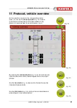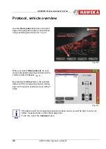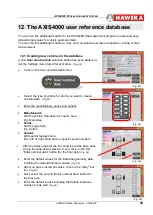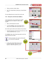
AXIS4000
W
HEEL
A
LIGNMENT
S
YSTEM
HAWEKA Wheel Alignment –AXIS4000
55
16 Special rims
Run-out compensation must be carried out for the indi-
vidual camera measurement heads for each vehicle axle
by selecting
Special rims
if you cannot be sure that the
wheel alignment clamp is correctly positioned in relation
to the wheel hub.
•
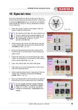
Place the camera measurement heads on the rim
flange of the first vehicle axle.
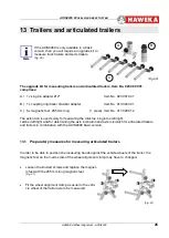
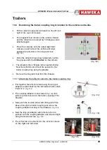
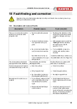
On vehicles with Trilex rims, the magnetic feet
must be replaced with a special adapter and
grab arms must be fitted to the wheel due to
the 3-part design of the rim.
(Fig. 123)
Item No. 924 000 004
•
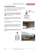
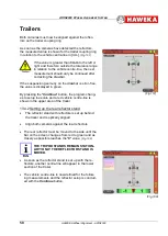
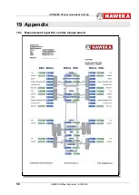
After selecting the vehicle, tick the special rims box
on the vehicle data overview screen and select the
"
Continue
" button.
(Fig. 124)
•
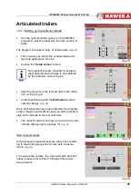
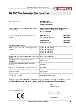
Run-out compensation will now be carried out for
the first wheel on the first axle on the following pro-
gram screen.
•
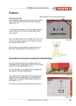
Follow the instructions on the left-hand edge of the
screen. Compensation is conducted in three stages
and is shown graphically.
(Fig. 125)
•
Lower the vehicle back onto the turning plate.
•
Then carry out run-out compensation on the same
axle of the opposite wheel.
•
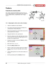
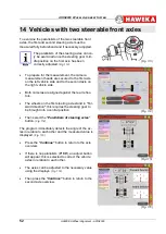
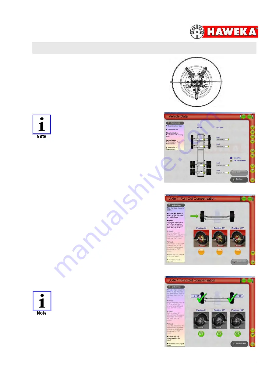
After completing this process, measuring of this one
vehicle axle can begin by pressing the "
Setup
scales
" button.
(Fig. 126)
•
Run-out compensation must be carried out again for
each wheel for every vehicle axle to be measured.
IF YOU SWAP VEHICLE AXLES DURING
MEASUREMENT (BY CLICKING THE BUT-
TON 1 / 2 / 3 ETC.), YOU WILL HAVE TO
CARRY OUT RUN-OUT COMPENSATION
AGAIN.
(Fig. 126)
(Fig. 124)
(Fig. 123)
(Fig. 125)

