AXIS4000
W
HEEL
A
LIGNMENT
S
YSTEM
HAWEKA Wheel Alignment –AXIS4000
29
Front axle measurement
•
A reflector stand is assembled and optically aligned in
front of and behind the vehicle.
•
Make sure that the reflector stands are close enough
to the vehicle and stand parallel to the rear of the ve-
hicle.
•
Once the reflector stands are positioned, the left and
right reflectors are fitted at the same position on the
stand. (Note the positioning boreholes on the stand)
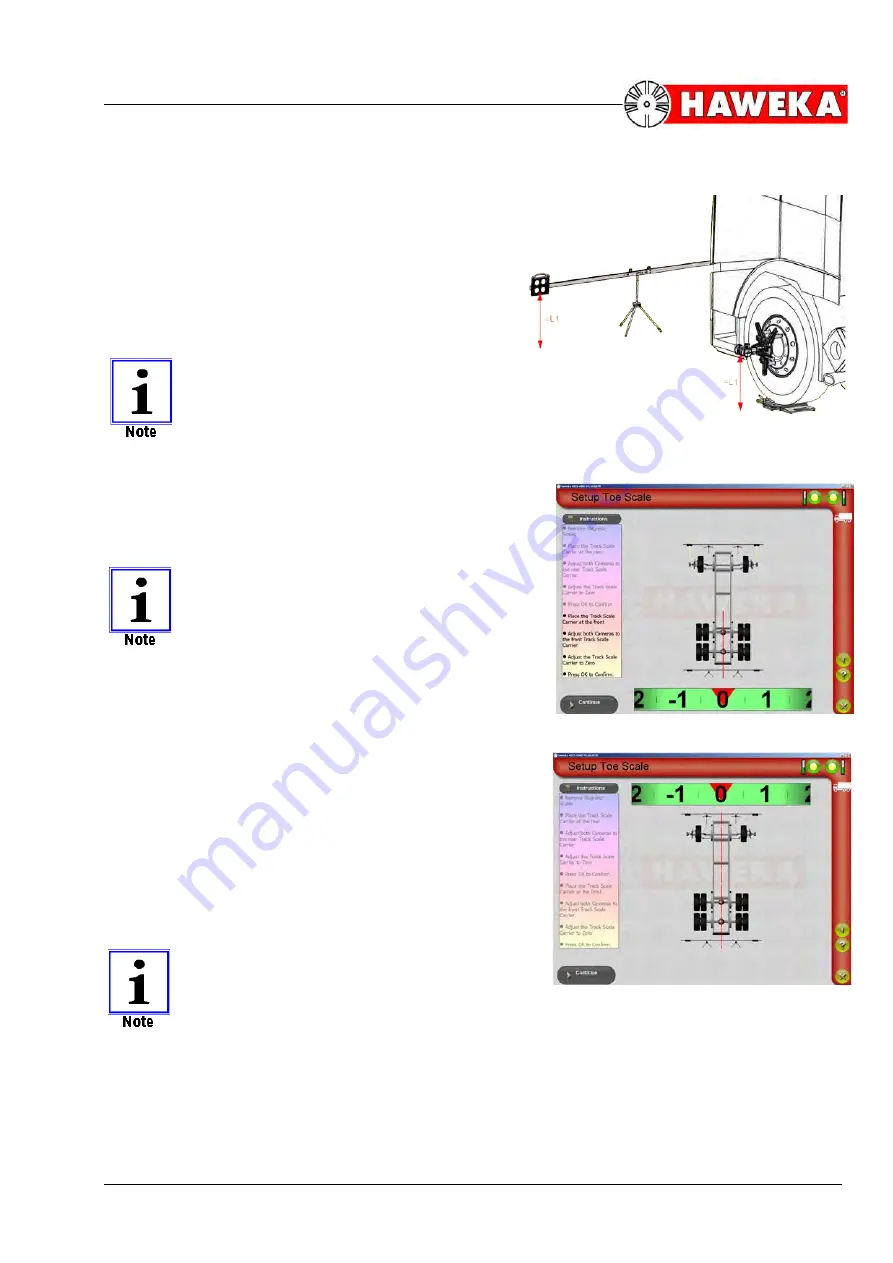
THE REFLECTORS MUST BE ALIGNED ON
A HORIZONTAL LINE WITH THE CAMER-
AS! (Fig. 34)
Height adjustment can be carried out using
the adjustable tripod stands.
Align the cameras to the rear reflectors.
•
The rear reflector must be moved to the side until the
bar on the screen changes from red to yellow to
green and as closely as possible reaches the "
0
" val-
ue.
(Fig. 35)
THE TRIPOD STANDS REMAIN STATION-
ARY! ONLY THE REFLECTOR STAND IS
MOVED.
•
As soon as the reflector stand is setup, a centre-line
is shown in this area of the vehicle. The program is
now ready for the reflectors of the second reflector
stand.
•
Now turn both cameras towards the front reflectors.
•
The bar on the screen displays a value again.
•
The front reflector stand must be moved to the side
until the bar on the screen changes from red to green
and as closely as possible reaches the "
0
" value.
•
Once this process is concluded, a centre-line will ap-
pear in this area as well. (A line is generated through
the entire vehicle.)
•
The vehicle centre-line is defined for the following
measurements and the reflector stand setup is con-
cluded with the
Continue
button.
(Fig. 36)
THE REFLECTOR STANDS SHOULD NOT
BE MOVED AGAIN FROM THEIR POSI-
TIONS FOR THE DURATION OF MEAS-
UREMENT.
If the position of the reflector stands is altered during measurement, they must be re-aligned. Meas-
urement can then be continued from the last measurement point.
(Fig. 36)
(Fig. 35)
(Fig. 34)


