31
V01 05/2016 1003370
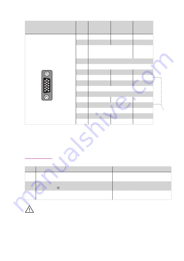
Table 31.1 Pin assignment, X7-encoder connection
Ill.
X7/Pin
Function
Sin/Cos and TTL
Absolute encod-
ers SSI/EnDat
2.1/2.2
Absolute
encoder
HIPERFACE®
1
A–
A–
REFCOS
2
A+
A+
+COS
3
+5 V, ±5 % at
I_OUT_MAX=250 mA controlled,
monitoring via sensor cable
7 to 12 V /
(typ. 11 V)
100 mA
4
R+ / Data +
5
R- / Data -
6
B–
B–
REFSIN
7
–
–
U
S
- Switch
8
GND
GND
GND
9
ϑ
- (PTC, KTY, Klixon) internally connected to X6/9.
1)
10
ϑ
+ (PTC, KTY, Klixon) internally connected to X6/5.
1)
11
B+
B+
+SIN
12
Sense +
U
S
- Switch
13
Sense –
–
14
–
CLK+
–
15
–
CLK–
–
The sum of the
currents
tapped
at X7/3 and
X6/4
must not
exceed
the specified
value!
After con-
necting
pin 7 to pin 12,
a voltage of
11.8 V is set
at X7/3 and
X6/4!
1)
Be sure to pay attention to the notice headed below!
Note:
The encoder supply at X7/3 is short-circuit proof in both 5 V and 11 V operation. The controller remains in operation
enabling the generation of a corresponding error message when evaluating the encoder signals.
Attention!
When connected to terminal X5, the motor temperature sensor must provide basic insulation, against the motor coil
and, when connected to terminal X6 or X7, must provide increased insulation in accordance with EN 61800-5-1.
3.13 Motor connection
Step
Action
Comment
1.
Specify the cable cross-section dependent on the maximum current and
ambient temperature.
Cable cross-section according to local and country-spe-
cific regulations and conditions
2.
Connect the shielded motor cable to terminals X1/ U, V, W and connect the
motor to ground at .
Mount shield at both ends to reduce interference
emission.
3.
Wire the motor temperature sensor and activate temperature evaluation
by means of DriveManager. See also related note.
Mount shield at both ends to reduce interference
emission.
Note:
In the event of a short-circuit or ground fault in the motor cable, the power stage is disabled and an error message is
issued.
Table 31.2
54321
10
9
876
15
14
13
12
11
X7
Encoder/ SSI


