background image

33

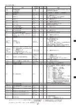
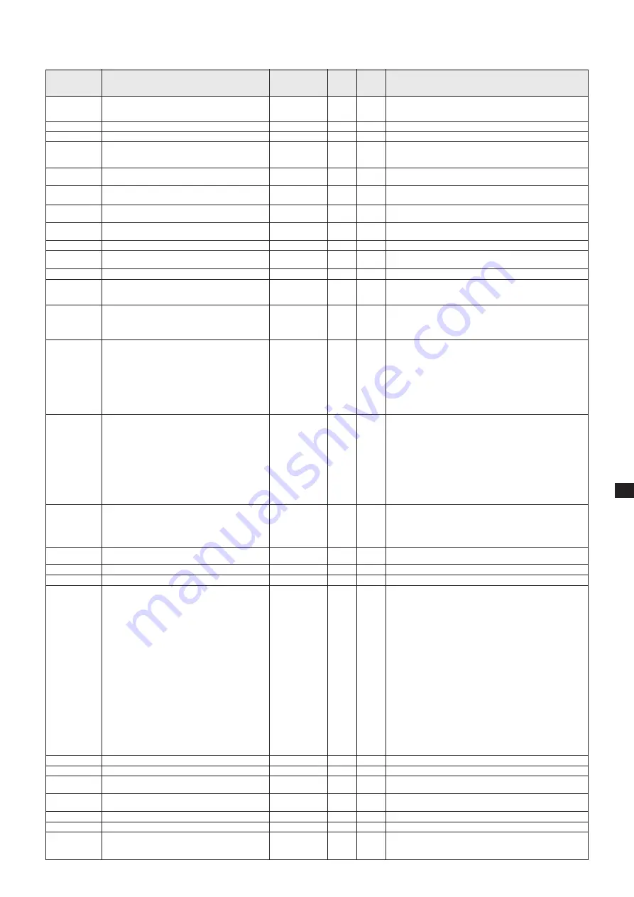
Table 2 : List of commands

Command

CNT0

CNT1

CNTQ
VER
L1

L0

S1

S0

AT***.*

ATQ
ATS

ATT
INT*


INTQ

INTSET***

or

INTSET*.**

CURE 

α β γ

 : 

nnn,mmm.m,...

or

CURE 

α β γ

 : 

nn.n,mmm.m,...

CUREQ 

α

START*

STPQ
STOP
INP

LIF
LAMPCLR
PROG_1STEP

PROG_7STEP

PROG_N1STEP
PROG_N7STEP
PROG?

Description

Control mode setting 

0: Front panel control

1: Command control
Inquiry of control mode
Version information
Lamp ON

Lamp OFF

Shutter OPEN

Shutter CLOSE

Shutter auto time setting

***.*(000.0 – 999.9 s)
Shutter auto time check
Shutter auto operation started

Shutter auto operation remaining time check
Diaphragm control : * is 0 to 4 numbers, meaning 

0: Stop, 1: UP, 2: DOWN 

3: UP (1point), 4: DOWN (1point)
Output intensity check

Output intensity setting

  ***: Output intensity (%)

  *.**: Output intensity (W)

The memory cure program of the program No. 

α

 is set by the unit of % if

 γ

=1 when using the 

shutter mode 

β

 and by the unit of W if

 γ

=2 when 

using the shutter mode 

β

.

  α

: Program number (1 – 9)

  β

: Shutter mode (1 or 2)

  γ

: Unit of output intensity being set (1: %, 2: W)

  nnn: Output intensity (%)

  n.nn: Output intensity (W)

  mmm.m: Time(s)

Comma division is used to link 7 steps.
Program number 

α

 memory cure program check

Program ** memory cure (setting in %) started

Memory cure progress state
Memory cure forced to end
Input pin data transmission 

Lamp operation time check
Accumulated lamp operation time clear
Program mode set to 1STEP

(Automatic recognition of Optical Feedback Unit)
Program mode set to 7STEP

(Automatic recognition of Optical Feedback Unit)
% display program mode setting forced to 1STEP
% display program mode setting forced to 7STEP
Inquiry of program mode

Character string 

returned  from 

light source  side

CNT0OK

CNT1OK

CNT*
VER**-**-**
L1OK

L1NGxx

L0OK

L0NGxx
S1OK

S1NGxx
S0OK

--
ATOK

ATNG03
AT***.*
ATSOK

ATSNGxx
ATT***.*
INT*OK

INT*NG 

INT***

INT*.**

INTSETOK

INTSETNGxx

CURE 

α β γ

 OK

CURE 

α β γ 

NG

CURE 

α β γ

 :

nnn,mmm.m,...

or

CURE 

α β γ

 :

n.nn,mmm.m,...
START*OK

START*NGxx
STP*
STOPOK
INP***

LIFOK****.*
LAMPCLROK

PROG_1STEPOK

PROG_7STEPOK

PROG_N1STEPOK
PROG_N7STEPOK
*STEP

 Handled  Handled

  by 

by

  1STEP  7STEP

  Yes 

Yes

  Yes 

Yes

  Yes 

Yes

  Yes 

Yes

  Yes 

Yes

  Yes 

Yes

  Yes 

Yes

  Yes 

No

  Yes 

No

  Yes 

No

  Yes 

No

  Yes 

Yes


  Yes 

Yes

  Yes 

No

  No 

Yes

  No 

Yes

  No 

Yes

  No 
  No 

Yes

  Yes 

Yes

  Yes 

Yes

  Yes 

Yes

  Yes 

Yes

  Yes 

Yes


  Yes 

Yes

  Yes 

Yes

  Yes 

Yes

Remarks

When using the front panel control, ERR is output for all 

commands other than this command.

The front panel control is used after the power is turned on.
* Control mode (0: from front, 1: from communication port)

NG trigger being applied (01)

Shutter is also closed at the same time if it is open.

If auto cure operation is at work, it is terminated (closed).
NG trigger being applied (01)

NG memory cure operation at work (02)

If memory cure operation is at work, it is terminated (closed).

If auto cure operation is at work, it is terminated (closed).
NG auto function being executed (03)

NG auto function being executed (03)

ATTOK00000.0 other than when being executed
NG memory cure operation at work (02)


***: Output intensity (%),  *.**: Output intensity (W)

Output intensity (W) is used when the optical feedback unit 

is connected and output intensity (%) is used when the opti-

cal feedback unit is unconnected.
NG shutter in auto-operation mode (03)

When the optical feedback unit is used and both conditions 

of (1) shutter closed, and (2) lamp ON are met, set the out-

put intensity and adjust the diaphragm so that the set output 

intensity value is obtained. If above conditions are not met, 

doesn’t set the output intensity. When the optical feedback 

unit is not used, set the output intensity regardless of the 

shutter and lamp conditions and adjust the diaphragm so 

that the set output intensity value is obtained.
NG memory cure operation at work (02)

α

: Program number (1 – 9), 

β

: Shutter mode (1 or 2)

γ

: Unit of output intensity being set (1: %, 2: W)

nnn: Output intensity (%), n.nn: Output intensity (W), mmm.

m: Time(s)

Comma division is used to link 7 steps.
NG memory cure operation at work (02)

* Current step (1 – 7, 0 when unexecuted)
Shutter is closed and diaphragm is also stopped.
*** represent hexadecimal characters. When they are con-

verted to binary characters, each bit corresponds with the 

status described below.

Bit0: 1: Lamp ON, 0: Lamp OFF

Bit1: 1: Lamp stable, 0: Lamp unstable

Bit2: 1: Shutter open, 0: Shutter closed

Bit3: 1: Diaphragm opening Min, 0: Otherwise

Bit4: 1: Diaphragm opening Max, 0: Otherwise

Bit5: 1: Initialize completed  0: Initialize going on

Bit6: 1: Lamp error  0: No error

Bit7: 1: Shutter error  0: No error

Bit8: 1: 4,000h (L8253:3,000h) accumulated time exceeded

         0: Not exceeded

Bit9: 1: Overheat alarm  0: No alarm

Bit10: 1: Lamp forced OFF because of overheating   

       0: Lamp not forced OFF or lamp ON again after the 

           overheat alarm is cancelled.

Bit11: 1: Set output intensity not obtained when optical

              feedback control is executed.

          0: Set output intensity being obtained or optical 

           feedback control not executed.

Transmitted as soon as the INP command is received or the signal changes.

**** *: Lamp operation time (hour), minimum resolution 1 h

* represents the current program mode

  1STEP: 1   % forced display 1STEP: N1

  7STEP: 7   % forced display 7STEP: N7

Explanation of NG

 ........... XX represent the NG content.

01: Lamp trigger being applied, 02: Memory cure being executed, 03: Shutter auto function being executed,  

04: Optical feedback unit unconnected, 05: Error not reaching memory cure setting of output intensity (W) 

* and X represent 1 character of ASCII


Example: when xx=01, the data being communicated is H’30H’31.

Содержание LIGHTINGCURE LC8

Страница 1: ...e unless this manual has been fully understood The person responsible for the equipment must not let anyone operate the equipment who does not have full understanding of the equipment Keep this manual...

Страница 2: ...2...

Страница 3: ...29 Adjustment of Optical Feedback Unit Option 32 Command Control 32 Contents of this manual are subject to change without prior notice Copying or quoting of this manual whether partially or as a whol...

Страница 4: ...APAN INPUT 100 V 240 V 300 VA 50 HZ 60 Hz IOIOI S N DB0000 MODEL L9588 01 SPOT LIGHT SOURCE MADE IN JAPAN INPUT 100 V 240 V 300 VA 50 HZ 60 Hz CN1 AC IOIOI Component Names L9566 L9566 series L9566 Fro...

Страница 5: ...connector page 32 oCooling fan 0Name plate position 1AC inlet 2Air inlets 3Light output adjusting screw page 32 zAlarm indicator page 24 xLamp ON indicator page 29 cLamp Operation time page 27 vRelati...

Страница 6: ...6 1 1 1 2 JIS C 7550 3 JIS T 8141 30 kV 15 1 MPa 10 4 MPa 40...

Страница 7: ...7 56 1 3 L9566 L9588 03 04 06A L9566 L9588 01A 02A 4000 L8253 3000 4000 L8253 3000 4000 L8253 3000 0 1 MPa 1 MPa IEC I ON OFF...

Страница 8: ...8 25 80 10 cm 10 cm L9566 L9588 10 cm 10 cm 10 cm 10 cm...

Страница 9: ...V 1 k GND 15 D sub w i GND ON o 4 GND ON 0 5 ON D sub 15P XM3A 1521 XM2S 1511 GND ON 50 V 30 mA GND ON ON 30 V 50 mA 100 1 k 50 V No 1 12 V 12 V dc 100 mA max 2 4000 L8253 3000 3 4 5 5 6 7 8 9 10 0 5...

Страница 10: ...10 SHUTTER ERR LAMP ERR LAMP ERR UP DOWN LAMP ERR OVER HEAT 2 4000 L8253 3000 LAMP CHANGE 5000 q w 10 cm OFF OFF 10 cm...

Страница 11: ...11 q OFF w e 1 MPa 10 r t y u...

Страница 12: ...12 Save Normal POWER SAVING Save Normal POWER SAVING Normal Save 10 q w M4 8 e r LIGHTNING CURE LC8 A9616 10 q w e r q r M3 2 w e L9588 L9566 M3...

Страница 13: ...13 0 1 MPa 1 MPa ON OFF ON OFF 10 q 15 w OFF e r t y 11 r u 4000 L8253 3000 LAMP CHANGE 5000 SHIFT UP DOWN OPERATING TIME UP DOWN 0 5000 10 OFF 30 ms 1 OFF 10 2 5...

Страница 14: ...14 LAMP ON OFF 1 1 5 0 5 ON e ON 3 19 5 STABLE 5 r ON LAMP ON OFF 1 5 2 0 5 0 5 ON e r OFF 2 9 SHUTTER MANUAL 1 SHUTTER MANUAL 1 3 5 ON t ON 3 5 OFF t OFF...

Страница 15: ...SELECT SHIFT SELECT SHIFT SELECT 3 w SHUTTER AUTO 7 7STEP 1 1STEP SHIFT SELECT W SHIFT 1STEP 1 W 3 1 7 STEP 7STEP 7 W 1 STEP 1 7 STEP 7 1 STEP 7STEP 1STEP 1STEP UP DOWN 0 100 1 SHUTTER MANUAL 0 00 W...

Страница 16: ...16 1 2 7STEP SELECT 1 9 SELECT 1 2 1 P1 P2 P3 P4 P5 P7 P6 1 P1 P2 P3 P4 P5 P7 P6 1 2 1 UP DOWN 0 100 1 SHUTTER MAN UAL 0 00 W 4 50 W 0 02 W UP DOWN 0 1 999 9 0 1 2 1 2 0 0 3 6 7 3 1...

Страница 17: ...SHIFT SELECT SHUTTER MANUAL r UP 3 LCD t SHIFT SELECT 3 SHUTTER MANUAL y SHUTTER MANUAL u i e t RS232C PC RS232C 1 9600 1 8 CR 0DH PC PC 1 INP 2 500 ms 50 ms 25 ms 20 ERR 1 PC ERR05 INP 2 ERR05 INP PC...

Страница 18: ...xx L0OK L0NGxx S1OK S1NGxx S0OK ATOK ATNG03 AT ATSOK ATSNGxx ATT INT OK INT NG INT INT INTSETOK INTSETNGxx CURE OK CURE NG CURE nnn mmm m CURE n nn mmm m START OK START NGxx STP STOPOK INP LIFOK LAMPC...

Страница 19: ...19 4000 L8253 3000 4000 L8253 3000 56 LAMP ERR UV 5000 PC 5 typ 11 11 13 13 11 17 18 13 15 16 10 11 11 15 14 14 17 17 17 10 17 PC 5...

Страница 20: ...operation of the equipment Never look directly into the light guide connection aper ture or at the light emanating from the light guide Strong ultraviolet light can cause visual disorder DO NOT allow...

Страница 21: ...orized When it is used and disposed of in any place outside of Japan it should be treated properly according to the statutory regulations of the state and local governments applicable to that place La...

Страница 22: ...ended environment for use About 25 C ambient temperature 80 or less humidity Allow for adequate ventilation of fan exhaust Some lamps depending on types produce ozone which smells for some time after...

Страница 23: ...g as it is inputted When no signal is inputted the shutter closes 14 Output intensity DOWN When this signal is inputted while the shutter is open using the manual mode the output intensity reduces as...

Страница 24: ...ndicator flashes The unit can be used for some time after this indi cator starts flashing replace the lamp with a new one as soon as possible After replacing the lamp be sure to reset the accu mulated...

Страница 25: ...he lamp flange so that the slit faces up as shown in the figure and push in the lamp as it is y After inserting the lamp fully align the groove in the lamp fixing cap and the pin of the lamp holder an...

Страница 26: ...to install a specified filter A9616 series to a unit of LIGHTING CURE LC8 series Filter Installation Be sure to disconnect the power cord when installing the filter Do not install the filter while the...

Страница 27: ...amp with a new one as soon as possible Also when the accumulated lamp operation time reach es 5000 hours the lamp is forced to turn off for the sake of safety Unless the accumulated lamp operation tim...

Страница 28: ...the power failure time is 30 ms or less The lamp remains on Everything functions normally When the power failure time is about 1 second The lamp goes off and both of the lamp ON signal and lamp stable...

Страница 29: ...flash for ap proximately 5 seconds If a panel button is pressed while the indicator lamp is flashing both the lamp and the indicator lamp go out The lamp does not go out unless the button is pressed t...

Страница 30: ...and select the mode using the SELECT button As the program mode once set is stored in the memory of the main unit the program starts in the previously set mode when the power is turned on next time U...

Страница 31: ...ty changes in steps Step 1 Output intensity setting display Adjust the output intensity diaphragm opening using UP and DOWN but tons 0 to 100 by every 1 When the optical feedback func tion is at work...

Страница 32: ...seconds or longer to exit the PROGRAM mode and press the SHUTTER MANUAL button to close the shutter y Press the MANUAL button of the shutter to open the shutter u Using a precision screwdriver turn th...

Страница 33: ...mory cure operation at work 02 If memory cure operation is at work it is terminated closed If auto cure operation is at work it is terminated closed NG auto function being executed 03 NG auto function...

Страница 34: ...ce the lamp with a new one Adjust the intensity Wipe the end faces of the light guide clean with a gauze soaked with alcohol Tighten the lamp fixing cap securely Lower output intensity setting value o...

Страница 35: ...35 1 1 1 2 IEC 2006 IEC 62471 EMI 30kV 15 1MPa 10 4MPa 40...

Страница 36: ...36 56 1 3 4000 L8253 3000 4000 L8253 3000 4000 L8253 3000 0 1MPa 1MPa IEC I ON OFF L9566 L9588 03 04 06A L9566 L9588 01A 02A...

Страница 37: ...37 L9566 L9588 10cm 10cm 10cm 10cm 25 80 10cm 10cm...

Страница 38: ...GND D sub 15P XM3A 1521 XM2S 1511 50V 100 GND 1k GND ON 50V 30mA GND 30V 50mA 100 1k No 1 12 V 12V dc 100 mA max 2 4000 L8253 3000 3 4 5 5 6 7 8 9 UP 10 0 5 11 0 5 12 0 5 13 14 DOWN 15 GND COM w i GN...

Страница 39: ...39 SHUTTER ERR LAMP ERR LAMP ERR UP DOWN LAMP ERR OVER HEAT 2 4000 L8253 3000 LAMP CHANGE 5000 q w 10cm OFF OFF 10cm...

Страница 40: ...40 q OFF w e r t y 1MPa 10 u...

Страница 41: ...41 Save Normal POWER SAVING Save Normal POWER SAVING Normal Save 10 q w M4 8 e r LIGHTNING CURE LC8 A9616 10 q w e r L9566 L9588 q r w e M3 2 M3 e...

Страница 42: ...42 0 1MPa 1MPa ON OFF ON OFF 10 q 15 w OFF e r t y 40 r u 4000 L8253 3000 LAMP CHANGE 5000 SHIFT UP DOWN OPERATING TIME UP DOWN 0 1 1 5000 30ms 1 OFF 10 2 5...

Страница 43: ...43 1 5 0 5 e ON 1 LAMP ON OFF 3 48 5 STABLE 5 r ON 1 LAMP ON OFF 5 2 0 5 0 5 e r OFF 2 9 2 1 SHUTTER MANUAL 1 SHUTTER MANUAL 3 5 t ON 3 5 t OFF...

Страница 44: ...SELECT SHIFT SELECT SHIFT SELECT 3 w SHUTTER AUTO 7 7STEP 1 1STEP SHIFT SELECT W 1STEP 1 W 7 STEP 7STEP 7 W 1 STEP 1 7 STEP 7 1 STEP 7STEP 1STEP 1STEP SHIFT 7STEP 3 1 UP DOWN 0 100 1 SHUTTER MANUAL 0...

Страница 45: ...45 1 2 SELECT 1 9 SELECT 1 2 1 P1 P2 P3 P4 P5 P7 P6 1 1 P1 P2 P3 P4 P5 P7 P6 2 1 2 1 2 0 0 3 6 7 3 1 1 UP DOWN 0 100 1 SHUTTER MANUAL 0 00W 4 50W 0 02W UP DOWN 0 1 999 9 0 1...

Страница 46: ...00ms 50ms 25ms 20 ERR 1 PC ERR05 INP Fig 2 ERR05 INP PC PC PC ERR05 INP q w UV e SHIFT SELECT SHUT TER MANUAL r UP 3 LCD t SHIFT SELECT 3 SHUTTER MANUAL y SHUTTER MANUAL u UV i 3 5 00 UV UV 00 15mm 44...

Страница 47: ...NTSETNGxx NG 03 CURE nnn mmm m CUREE nn n mmm m 1 2 W 1 9 1 or 2 1 2 W nnn n nn W mmm m s 7 CURE OK CURE NG NG 02 CURE CURE nnn mmm m CUREE n nn mmm m 1 9 1 or 2 1 2 W nnn n nn W mmm m s 7 START START...

Страница 48: ...48 56 4000 L8253 3000 4000 L8253 3000 40 5000 40 42 42 40 PC PC 46 47 42 44 45 39 40 LAMP ERR 40 46 5 43 43 UV 5 46 46 46 39 46...

Страница 49: ...10 seconds later more than 1 sec The initial state is resumed Ultravi olet leakage Not above 0 001 mW cm2 at 365 nm Paint Standard paint color used at HAMAMATSU PHOTON ICS Displays Back side printed f...

Страница 50: ...V 240 V 300 VA 50 HZ 60 Hz IOIOI 142 110 16 16 227 5 311 232 39 5 39 5 36 12 7 49 49 158 49 49 311 232 39 5 39 5 36 12 7 142 110 16 16 227 5 158 S N DB0000 MODEL L9588 01 SPOT LIGHT SOURCE MADE IN JAP...

Страница 51: ...9616 11 2 230 250 60 248nm Accessories Option Specifications of filters 50 5 123 118 3 mm UNIT mm mm A9616 A9616 series A9616 mm UNIT mm mm 8 7 55 53 7 27 5 68 2 46 Filter Type Number of Transmittance...

Страница 52: ...1 50 million times of shutter operation Shutter Unit Optical Feedback 365 nm E9793 02 50 million times of shutter operation or 20 000 h Shutter Unit Optical Feedback 436 nm E9793 03 50 million times o...

Страница 53: ...service life such as lamp shutter and relay specified by each manu facturer has expired The extent of the warranty shall be limited to delivery of a sub stitute unit The warranty period of the substit...

Страница 54: ...54...

Страница 55: ...55...

Страница 56: ...gerstr 10 D 82211 Herrsching am Ammersee Germany Telephone 49 8152 375 0 Fax 49 8152 2658 E mail info hamamatsu de Denmark Office Lautruphoj 1 3 DK 2750 Ballerup Denmark Telephone 45 70 20 93 69 Fax 4...

Отзывы: