Page 22
4.
Heat Pumps
Programmable Energy Saver Modules are compatible with heat pumps, however, the savings gained by setting the heat pump
back may be erased by the auxiliary heaters when the heat pump tries to recover from the setback. A PESM will work best
with heat pumps that have one or more of the following features:
a.
An outdoor temperature switch that prevents the auxiliary heat from coming on unless it is very cold outside. This is
sometimes called a "heat balance" switch.
b.
A thermostat that uses rate of rise to determine if auxiliary heat is necessary: The Enerstat Model DSL-450. When
recovering from setback, the thermostat runs the heat pump first. It will run the auxiliary heat only if the rate of
temperature rise is less than 6 degrees F. per hour.
c.
An alternative auxiliary heat source that is inexpensive (i.e. gas).
These features will avoid the use of auxiliary heat (usually an electric strip heater) which is more expensive than using the
heat pump when recovering from setback. In general, heat pumps take a longer time to recover from setback, so it may be
advantageous to program a setback only for extended periods, such as a vacation.
OUTDOOR TEMPERATURE, TEMPERATURE SENSORS
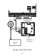
The Model 14A00 is a temperature sensor that can mount in an outdoor location, usually under an overhang, and sends the
outdoor temperature to an OmniLT system. It is coated with a sealant to withstand outdoor moisture. The outdoor temperature
can be displayed on the console, spoken over the telephone, or displayed on an HAI communicating thermostat.
1.
Each Model 14A00 Temperature Sensor requires one zone input.
-
Program the zone type as an Outdoor Temperature (Type 81). It may also be programmed as a Temperature (Type 82),
or Temperature Alarm (Type 83).
2.
Plan to mount the Model 14A00 under an overhang or to the underside of an eave, otherwise known as the soffet, to protect it
from direct sunlight and rain. Run a 4-conductor wire from the HAI controller to the selected location.
3.
Connect the red conductor to AUX 12V, the black conductor to AUX GND, and yellow conductor to the Zone (Z1-Z24)
using the 3 B-GEL watertight wire splices. The green conductor is not used.
4.
Mount the 14A00 using the 2 - #6 x 1/2" stainless steel self-tapping screws.
Содержание OmniLT Automation
Страница 1: ...Installation Manual Document Number 21I00 1 Rev A October 2000 ...
Страница 48: ...HAI New Orleans LA U S A ...


