


34
Installation and Maintenance Manual, Compact CA
Installation
D A
B
C
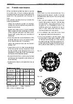
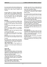
Fig. 3.25b
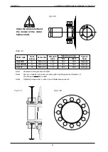
**SAE coupling J 518 C, code 6, 414 bar (6000 psi).
*** A-connection and C-connection is blocked at delivery. They are able to withstand max pressure.
*Not valid for motors prepared for displacement shift.
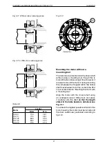
Fig. 3.25
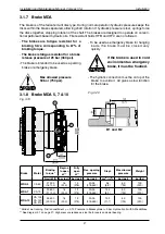
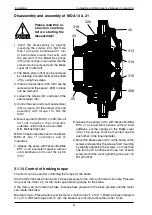
When using (heavy wall) piping and in frequent
reversal drives, it is recommended to fit flexible
hoses between the motor and piping to avoid
damage due to vibration and to simplify
installation of the motor. The length of the
hoses should be kept fuirly short.
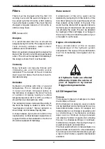
3.2
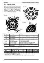
Oil connections
D3
F1
Fig. 3.25a
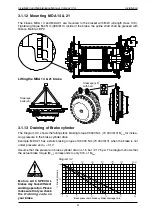
A, B, C and D: Connections for -speed valve. See fig. 3.5b
***
C
A
D
y
D1
C1*
F3
F4
A1*
T
x
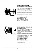
Connection
Description
Remarks
C1*, C
Main connection
If C is used as the inlet, the motor shaft rotates clockwise,
viewed from the motor shaft side*.
A1*, A
Main connection
If A is used as the inlet, the motor shaft rotates counter-
clockwise, viewed from the motor shaft side*.
D1
Drain outlet
Normally plugged at delivery.
D, D3
Alternative drain outlets
Normally plugged at delivery.
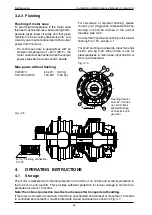
F1
Flushing connection
For flushing of radial lip seal. Normally plugged.
F3, F4
Flushing connection
For flushing of axial bearing and motor case.
T
Test connections
Used to measure pressure and/or temperature at the
main connections.
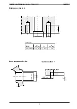
Motor
A**
C**
D1, D2
D3
F1, F3,
F4
T
y mm
y in
x mm
x in
CA 50...10 1 1/4" 1 1/4"
G 3/4"
G 3/4"
G 1/4"
G 1/4"
188
7,40
99
3,90


