1
Installation and Maintenance Manual, Compact CA
Motor
CA50/70
CA100/140
CA210
Tooth profile
and bottom
form
DIN 5480
DIN 5480
DIN 5480
Tolerance
8f
8f
8f
Guide
Back
Back
Back
Pressure angle
30°
30°
30°
Module
5
5
5
Number of
teeth
6
8
Pitch diameter
Ø 110
Ø 130
Ø 140
Minor diameter
Ø 109
Ø 19
Ø 139
Major diameter
Ø 119
Ø139
Ø 149
Measure over
measuring pins
19,781
149,908
159,961
Diameter of
measuring pins
Ø 10
Ø 10
Ø 10
Addendum
modification
X M
+,5
+,5
+,5
Spline
Thread for mounting tool
0
-1,6
0
-0,50
-0,083
-0,147
-0,085
-0,150
0
-1,6
0
-0,0
0
-0,50
0
-1,6
Table 3.3
-0,085
-0,150
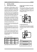
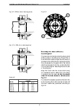
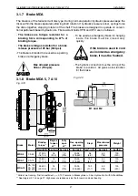
The splines shall be lubricated with hydraulic
oil, or filled with transmission oil from the
connected gearbox. To avoid wear in the
splines, the installation must be within the
specified tolerances in fig. 3.3. If there is no
radial or axial force on the shaft, the shaft can
be oiled only.
For production of the shaft, see 78 30,
78 31, 78 3, 78 33, 78 34,
78 35, 78 36, 78 38 and 78 39.
For control of spline see table 3.3.
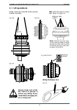
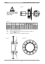
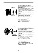
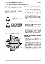
To make it easier to mount the motor on
the driven shaft end or to remove the motor
from the shaft it is recommended that a hole
(Table 3.4) should be drilled and tapped in the
centre of the shaft for a mounting tool; see
3.1.4 "Mounting the motor onto the driven
shaft", and 3.1.5 "Removing the motor from
the driven shaft".
The tool has both a UNC thread and a metric
thread, so that the hole can be drilled and
tapped to conform to one of the two alternatives
given in table 3.4.
Installation
Fig 3.3
Table 3.4 Alternative thread (Fig.3.1 and 3.2)
Unidirectional drives
Bidirectional drives
Steel with yield strength
Rel
mm
= 450 N/mm
Steel with yield strength
Rel
mm
= 700 N/mm
CA 50-210
D
E
F
G
M0
>17 (0,67)
5 (0,98)
50 (1,97)
UNC 5/8"
>13,5 (0,53)
(0,87)
30 (1,18)
(0.008)
(0.006)


