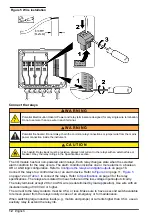
Terminal connections to the mains circuit in permanent connection applications must have insulation
rated for a minimum of 300 V, 60 °C (140 °F). Terminals connected to the mains circuit with a power
cord connection must be double insulated and rated 300 V, 60 °C (140 °F) at both the inner and
outer insulation levels.
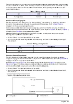
Table 1 Wiring—relays
NC
COM
NO
Normally closed
Common
Normally open
Connect the analog inputs
The I/O module has two analog inputs. Connect auxiliary instruments (e.g., third-party ultrasonic
sensor) to the analog inputs to supply measurements to the sampler. Refer to
on page 3 for the analog input specifications.
Connect one auxiliary instrument to each analog input with 24 to 16 AWG wire. Use 19 AWG to
16 AWG wire instead if the wire is 7.62 m (25 ft) long or more. Refer to
on page 12 and
Make connections with twisted-pair shielded wire. Connect the shield to a stud on the conduit
backing plate or at the far end of the cable.
• Do not connect the shield at both ends of the cable.
• Use of non-shielded cable may result in radio frequency emission or susceptibility levels higher
than allowed.
Table 2 Wiring—analog inputs
Pin
Description
IN # HI
+
IN # LO
–
Connect the analog outputs
The I/O module has three isolated 0–20 mA or 4–20 mA analog outputs. Configure the analog
outputs to supply a measurement from the sampler to an external instrument. Refer to
on page 3 for the analog output specifications.
Refer to
and
to connect the analog outputs. Refer to
on page 11 and
on page 12 to make wiring connections. Make connections with twisted-pair shielded wire
and connect the shield to a ground stud on the conduit backing plate.
• Do not connect the shield at both ends of the cable.
• Use of non-shielded cable may result in radio frequency emission or susceptibility levels higher
than allowed.
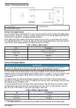
Figure 6 I/O module-powered loop
1
Analog output
2
External device
English
13
Содержание IO9000
Страница 2: ...English 3 Français 19 Español 37 Português 54 中文 72 日本語 88 2 ...
Страница 7: ...Figure 2 Wall mounting English 7 ...
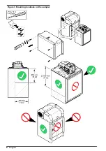
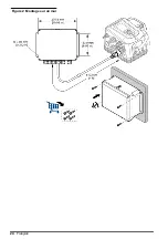
Страница 8: ...Figure 3 Mounting locations on the sampler 8 English ...
Страница 24: ...Figure 2 Montage sur un mur 24 Français ...
Страница 25: ...Figure 3 Emplacements de montage sur l échantillonneur Français 25 ...
Страница 42: ...Figura 3 Ubicaciones de montaje en el tomamuestras 42 Español ...
Страница 59: ...Figura 2 Montagem na parede Português 59 ...
Страница 60: ...Figura 3 Locais de montagem no amostrador 60 Português ...
Страница 76: ...图 2 墙面安装 76 中文 ...
Страница 77: ...图 3 采样仪上的安装位置 中文 77 ...
Страница 79: ...拆下护盖 按照如下图示步骤拆下护盖 布线概述 图 4 显示了布线连接以及保险丝位置 请参阅 图 5 准备和安装电线 中文 79 ...
Страница 93: ...図 3 サンプラーの取り付け場所 日本語 93 ...
Страница 95: ...カバーの取り外し 次の図の手順に示されているように カバーを取り外します 配線の概要 図 4 は ワイヤの接続部とヒューズの場所を示しています 配線を用意して取り付けるには 図 5 を 参照してください 日本語 95 ...
Страница 105: ......


