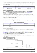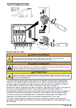
Table 4 Wiring—digital outputs (continued)
Pin
Description
COM
Common
PULLUP V
+25 VDC maximum
4
COM (pin 14)
Common for PULLUP V
Install the covers
Install the covers with the supplied hardware to keep the protection supplied by the enclosure. Refer
to
on page 10. Make sure that the covers are tightly closed.
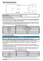
Connect to the sampler
Connect the I/O module cable to the AUX I/O port of the sampler. Refer to
Figure 8 Connect to the sampler
Configuration
Configure the AUX I/O port
1.
Push
MENU
.
2.
Select Hardware Setup>AUX and I/O Port>Type>I/O Module.
Enable the relays
Enable the relays that are connected to external instruments.
1.
Push
MENU
.
2.
Select AC Relays.
3.
Select the applicable relays.
4
Sets the logic high voltage for the digital outputs.
English
15
Содержание IO9000
Страница 2: ...English 3 Français 19 Español 37 Português 54 中文 72 日本語 88 2 ...
Страница 7: ...Figure 2 Wall mounting English 7 ...
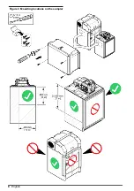
Страница 8: ...Figure 3 Mounting locations on the sampler 8 English ...
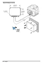
Страница 24: ...Figure 2 Montage sur un mur 24 Français ...
Страница 25: ...Figure 3 Emplacements de montage sur l échantillonneur Français 25 ...
Страница 42: ...Figura 3 Ubicaciones de montaje en el tomamuestras 42 Español ...
Страница 59: ...Figura 2 Montagem na parede Português 59 ...
Страница 60: ...Figura 3 Locais de montagem no amostrador 60 Português ...
Страница 76: ...图 2 墙面安装 76 中文 ...
Страница 77: ...图 3 采样仪上的安装位置 中文 77 ...
Страница 79: ...拆下护盖 按照如下图示步骤拆下护盖 布线概述 图 4 显示了布线连接以及保险丝位置 请参阅 图 5 准备和安装电线 中文 79 ...
Страница 93: ...図 3 サンプラーの取り付け場所 日本語 93 ...
Страница 95: ...カバーの取り外し 次の図の手順に示されているように カバーを取り外します 配線の概要 図 4 は ワイヤの接続部とヒューズの場所を示しています 配線を用意して取り付けるには 図 5 を 参照してください 日本語 95 ...
Страница 105: ......


