Habasit Italiana S.p.A.
Vittorio Veneto 31029 (TV)
Tel.: ++39(0)438.9113
Fax. ++39(0)438.200545
Regulating Unit PMR-07
Author:
A.T. / KM
CONNECTIONS
Edition: 04/2006
Page
F-7
Replaces: 10/2005
F.3.2
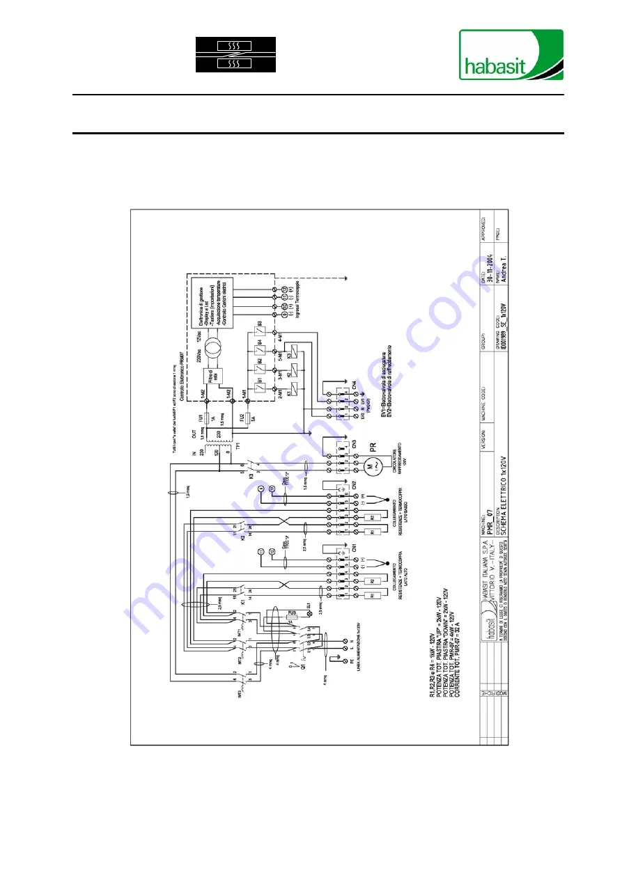
C
IRCUIT DIAGRAM OF
PMR-07
-
120V
F
IGURE
11
-
E
LECTRIC LAYOUT
PMR-07
-
120V
Regulating Unit PMR-07


