


APS-1102A User Manual
APS-1102A
4-24
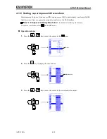
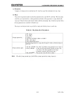
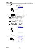
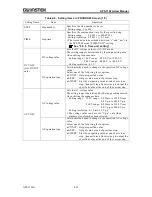
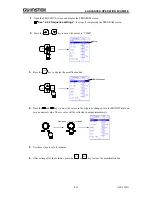
The step transition parameters specify the next step and its timing.
Table4-5. Step Transition Parameters
[Step time]
Specified in time
[Step end phase]
Sets step end phase as enabled or disabled.
[Step end]
The following parameters are provided to specify the action at the end of the
step.
Continue sequence (CONT)
Hold (HOLD)
Idle (STOP)
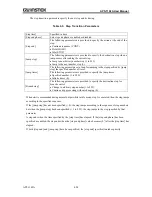
[Jump step]
The following parameters are provided to specify the destination step when a
jump occurs after ending the current step.
Jump to an arbitrary number step (1 to 255)
Jump to the next number step (0)
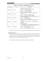
[Jump times]
The following parameters set a loop for jumping to the step specified by [jump
step] the specified number of times.
The following parameters are provided to specify the jump times.
Specified number (1 to 999)
Infinite times (0)
[Branch step]
The following parameters are provided to specify the destination step for
branch control.
Change to arbitrary step number (1 to 255)
Continue step processing without changing (0)
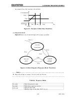
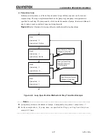
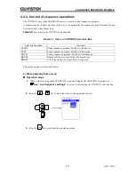
When start is commanded during normal output while in idle mode, step 1 is executed, then the step jumps
according to the specified sequence.
If the [jump step] has not been specified (= 0), the step jumps according to the sequence of step numbers,
but when the [jump step] has been specified (= 1 to 255), the step jumps to the step specified by that
parameter.
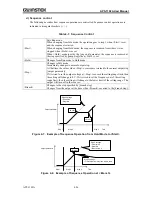
A step ends when the time specified by the [step time] has elapsed. If the [step end phase] has been
specified as enabled, the step ends when the [step end phase] value becomes (0
) after the [step time] has
elapsed.
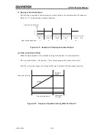
If both [step end] and [jump step] have been specified, the [step end] specification takes priority.
Содержание APS-1102A
Страница 15: ...Tables APS 1102A xiii ...
Страница 16: ......
Страница 24: ......
Страница 34: ...APS 1102A User Manual APS 1102A 2 10 2 5 Calibration To calibrate the APS 1102A contact GW Instek or our agent ...
Страница 72: ...APS 1102A User Manual APS 1102A 3 38 ...
Страница 184: ...APS 1102A User Manual APS 1102A 5 50 ...
Страница 242: ...APS 1102A User Manual APS 1102A 6 58 ...
Страница 266: ...APS 1102A User Manual APS 1102A 8 8 ...