9
SPECIFICATIONS
APS-1102A
9-7
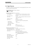
9.4 Signal Sources
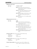
The signal sources that can be selected are internal (INT), external signal input (EXT), in external
(ADD), and external synchronization (SYNC).
a) Internal signal source
(INT mode, ADD mode)
See “9.1 Output”.
b) External signal input
(EXT mode, ADD mode)
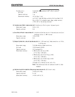
Gain setting range:
100 V range: 0.0 times to 220.0 times (initial value: 100.0)
200 V range: 0.0 times to 440.0 times (initial value: 200.0)
Gain setting resolution:
0.1 times
Gain accuracy:
5% (DC, or 45 Hz to 65 Hz, gain is at initial value, with rated
voltage output, no load)
Output phase to input:
In-phase
Input terminal:
BNC connector (rear panel)
(also used as the external sync signal input terminal)
Input impedance:
10 kΩ
Input voltage range:
2.2 V to +2.2 V
Nondestructive maximum
input voltage:
10 V
Frequency range:
DC to 550 Hz (sine wave)
DC to 100 Hz (other than sine wave)
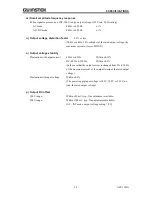
c) External synchronization
(SYNC mode)
Synchronization signal source:
External sync signal or line (select one)
Synchronization frequency range:
40 Hz to 500 Hz
Input terminal:
BNC connector (rear panel)
(also used as the external signal input terminal)
Note:
External sync signal is not required when line
synchronization is selected
Input impedance:
10 kΩ
Input voltage threshold value:
TTL
Minimum pulse width:
3 ms
Nondestructive maximum
input voltage:
10 V
Содержание APS-1102A
Страница 15: ...Tables APS 1102A xiii ...
Страница 16: ......
Страница 24: ......
Страница 34: ...APS 1102A User Manual APS 1102A 2 10 2 5 Calibration To calibrate the APS 1102A contact GW Instek or our agent ...
Страница 72: ...APS 1102A User Manual APS 1102A 3 38 ...
Страница 184: ...APS 1102A User Manual APS 1102A 5 50 ...
Страница 242: ...APS 1102A User Manual APS 1102A 6 58 ...
Страница 266: ...APS 1102A User Manual APS 1102A 8 8 ...

